
Image integration unit and image integration method

a technology of image integration and image, which is applied in the field of image integration unit and image integration method, can solve the problems that the technology disclosed in patent document 1 cannot be applied to a camera installed on a vehicle, and it is difficult to obtain three-dimensional information of a moving body, such as a vehicle and a pedestrian, and achieve the effect of accurate integration and high precision

Inactive Publication Date: 2012-01-19
KONICA MINOLTA INC
View PDF1 Cites 27 Cited by
  • Summary
  • Abstract
  • Description
  • Claims
  • Application Information

AI Technical Summary

Benefits of technology

[0006]With the foregoing in view, it is an object of the present invention to provide an image integration unit and image integration method, which can integrate time-series images imaged while moving, at high precision.
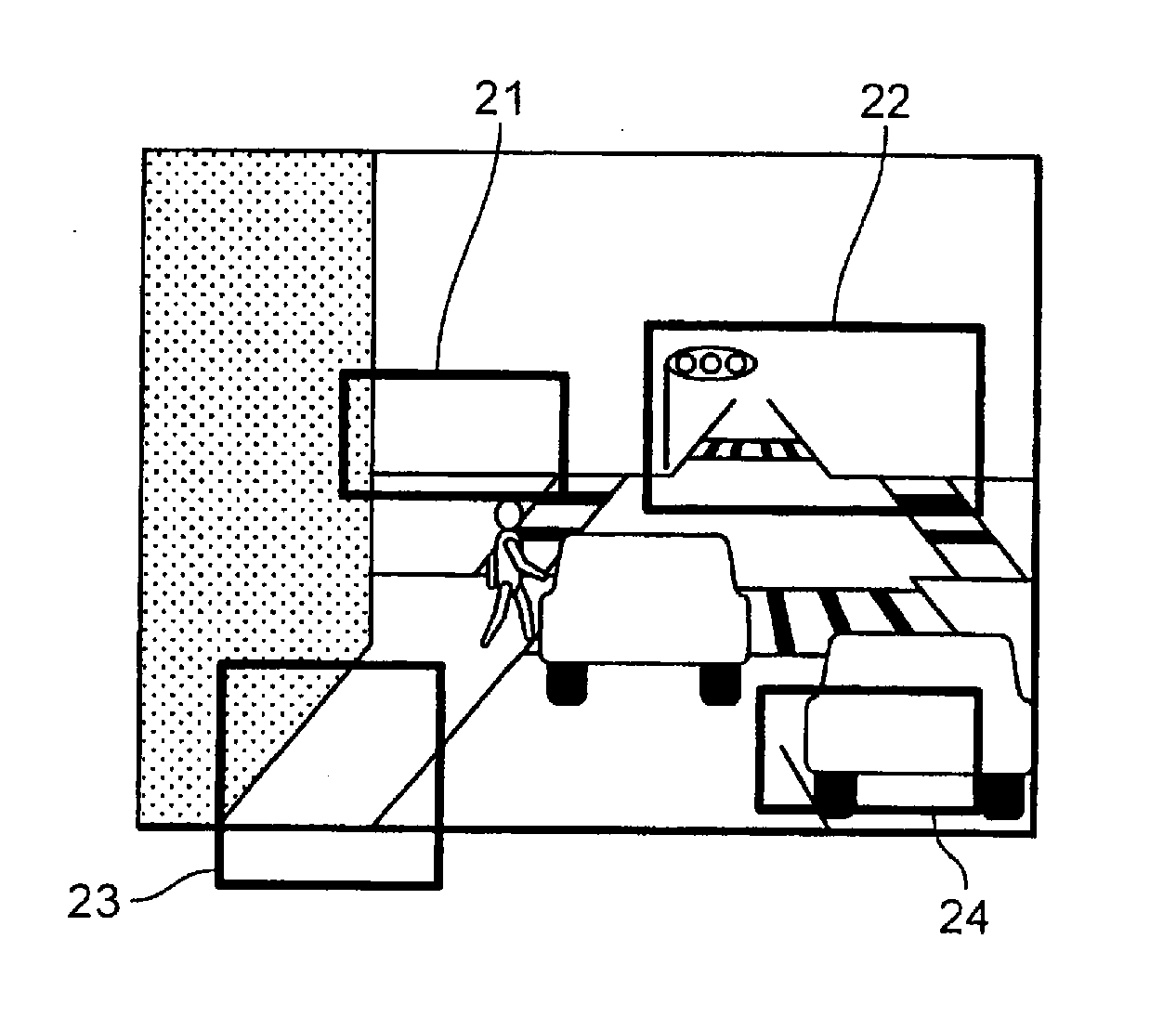
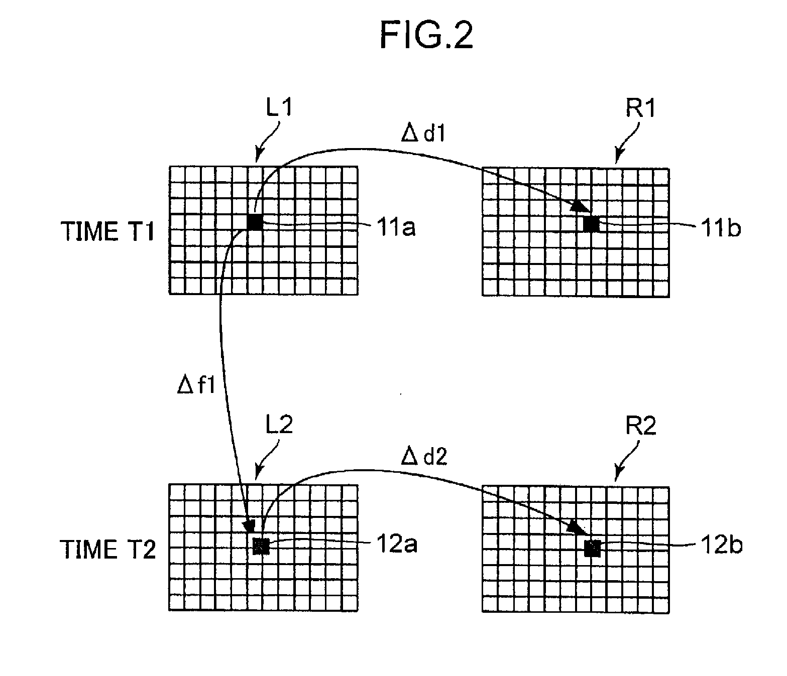
[0007]The image integration unit of the present invention extracts a stationary body area from each time-series image, and integrates the time-series images by matching the corresponding stationary body areas between the time-series images. Thereby the time-series images, including the images of moving bodies and stationary bodies, can be accurately integrated.

Problems solved by technology

This means that the technology disclosed in Patent Document 1 cannot be applied to a camera installed on a vehicle, which is a moving body.
The technology disclosed in Patent Document 2 is not a technology assuming the use for analyzing the situations of an accident, and can obtain only three-dimensional information of a stationary body.
Therefore in the case of the technology disclosed in Patent Document 2, it is difficult to obtain three-dimensional information of a moving body, such as a vehicle and a pedestrian, even if three-dimensional information of such stationary bodies as a road surface, traffic lights and traffic signs, can be obtained.

Method used


Image

  • Image integration unit and image integration method
  • Image integration unit and image integration method
  • Image integration unit and image integration method

Examples


Embodiment Construction

[0016]An embodiment of the present invention will now be described with reference to the drawings. In each drawing, composing elements denoted with a same reference numerals are a same composing element, and redundant description thereof is omitted.

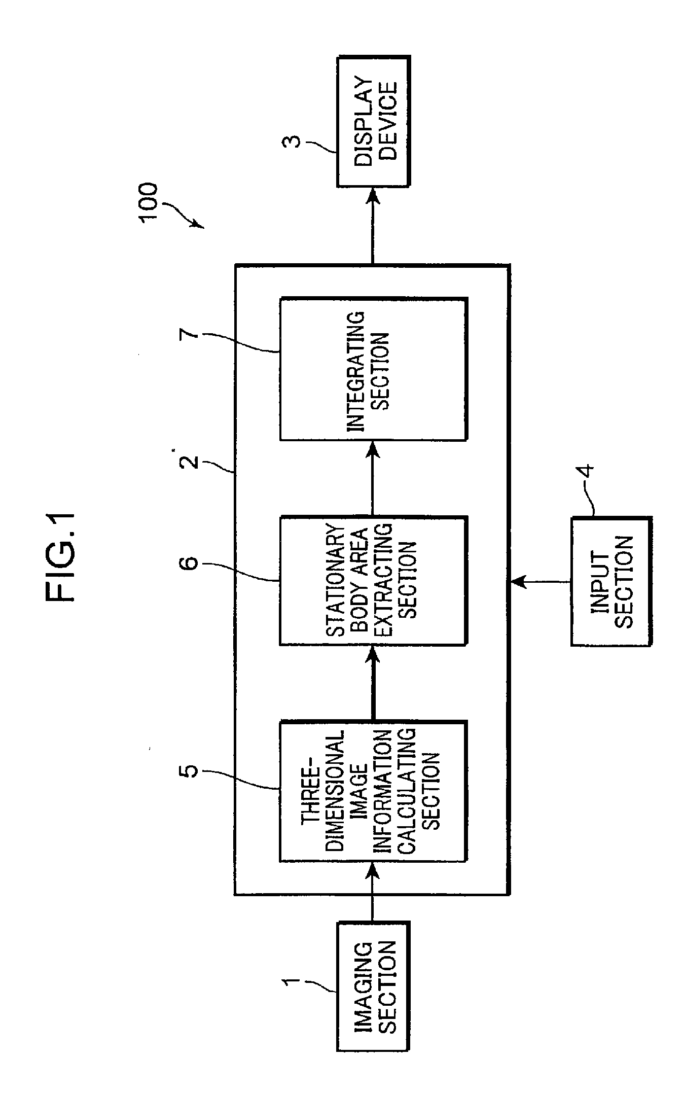
[0017]First a configuration of an image integration unit according to an embodiment of the present invention will be described. FIG. 1 is a block diagram depicting the configuration of the image integration unit according to an embodiment of the present invention. As FIG. 1 shows, the image integration unit 100 is provided with an imaging section 1, a processing section 2, a display device 3, and an input section 4. The imaging section 1 is installed in such a moving body as a vehicle, and obtains time-series images. The imaging unit 1 is a camera having such a image sensor as a CCD (Charge-Coupled Device). The imaging section 1 is preferably a stereo camera constituted by two cameras, which are disposed at the left and right with an appr...


PUM


Abstract

An image integration unit includes: an imaging section which is installed in a moving body and which images a plurality of time-series images at different times; a three-dimensional image information calculating section which calculates three-dimensional image information in each of the time-series images based on the time-series images imaged by the imaging section; a stationary body area extracting section which extracts stationary body areas in each of the time-series images based on the three-dimensional image information; and an integrating section which calculates the corresponding stationary body areas between the time-series images from each of the stationary body areas extracted in each of the time-series images, and matches the corresponding stationary body areas to integrate the time-series images.

Description

TECHNICAL FIELD[0001]The present invention relates to an image integration unit and an image integration method for integrating time-series images.BACKGROUND ART[0002]Recently research on various systems for improving safety is ongoing in the automobile industry. In particular, a crisis avoidance system using an image sensor having an imaging apparatus has been developed. Specifically, a system which specifies an obstacle around a vehicle and which analyzes the movement of the obstacle based on images imaged by the imaging apparatus, whereby the vehicle avoids the obstacle, has been developed.[0003]A system which extracts various information that is useful for investigating a cause of an accident by analyzing images before and after the accident has also been developed for cases when a crisis could not be avoided and an accident occurred. For example. Patent Document 1 discloses a system which obtains images before and after an accident using an imaging apparatus disposed at an inte...

Claims


Application Information

Patent Timeline
IPC IPC(8): H04N13/02
CPCB60R1/00B60R2300/107B60R2300/30G06T2207/30252G06T2207/10021G06T7/2033G06T2207/20048G06T7/246
Inventor SUMITOMO, HIRONORI
Owner KONICA MINOLTA INC
Learn More