Alternating Beam Laser Imaging System with Reduced Speckle

a laser imaging and alternating beam technology, applied in projectors, instruments, color television details, etc., can solve the problems of large power consumption, large image artifacts, and large power consumption, and achieve the effect of reducing the amount of power consumption, and reducing the amount of specks

Inactive Publication Date: 2012-01-19
MICROVISION
View PDF5 Cites 20 Cited by
  • Summary
  • Abstract
  • Description
  • Claims
  • Application Information

AI Technical Summary

Problems solved by technology

These systems consume small amounts of power, yet deliver bright, complex images.
One practical drawback associated with using lasers in projection systems is the image artifact known as “speckle.” Speckle occurs w

Method used


Image

  • Alternating Beam Laser Imaging System with Reduced Speckle
  • Alternating Beam Laser Imaging System with Reduced Speckle
  • Alternating Beam Laser Imaging System with Reduced Speckle

Examples


Embodiment Construction

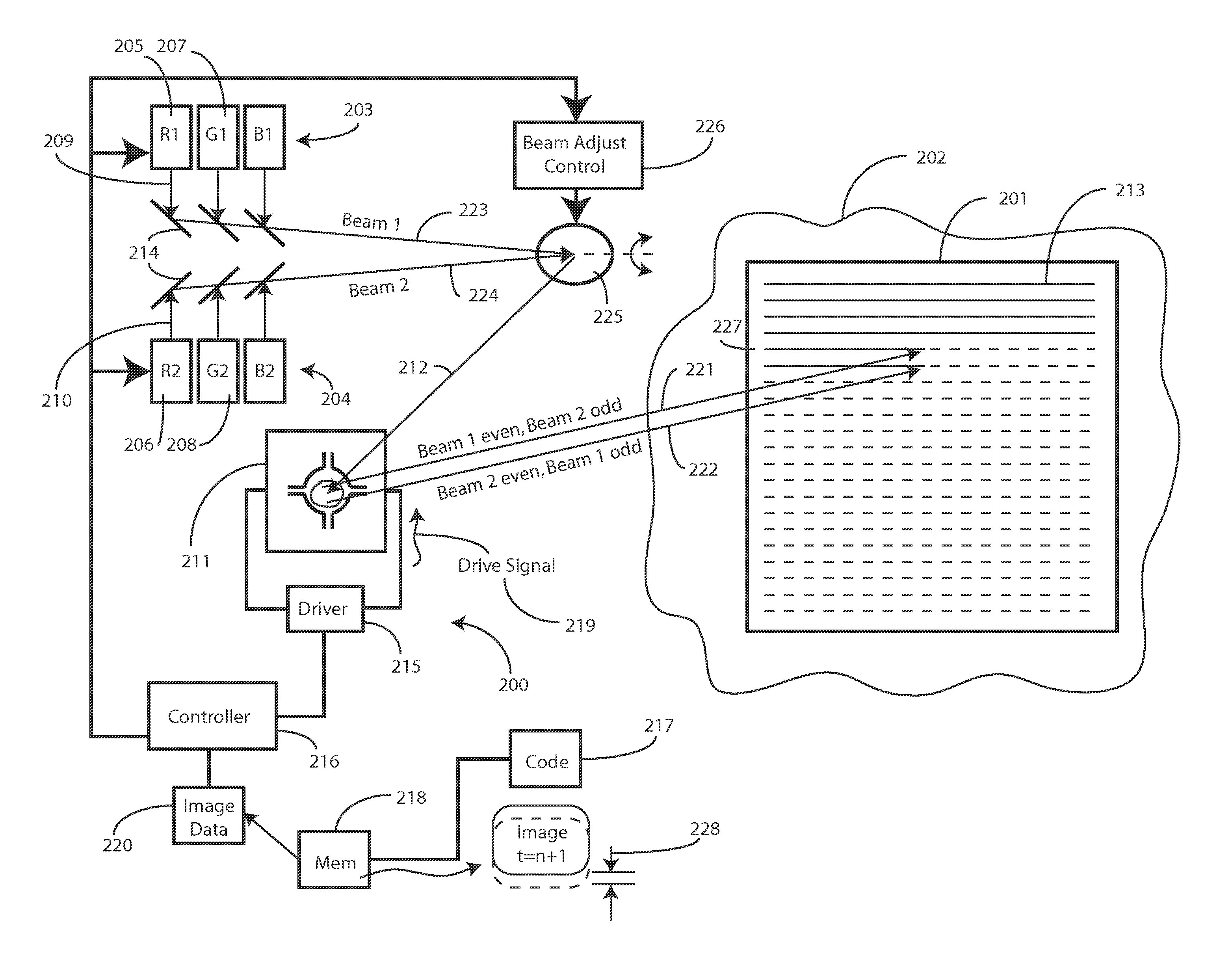
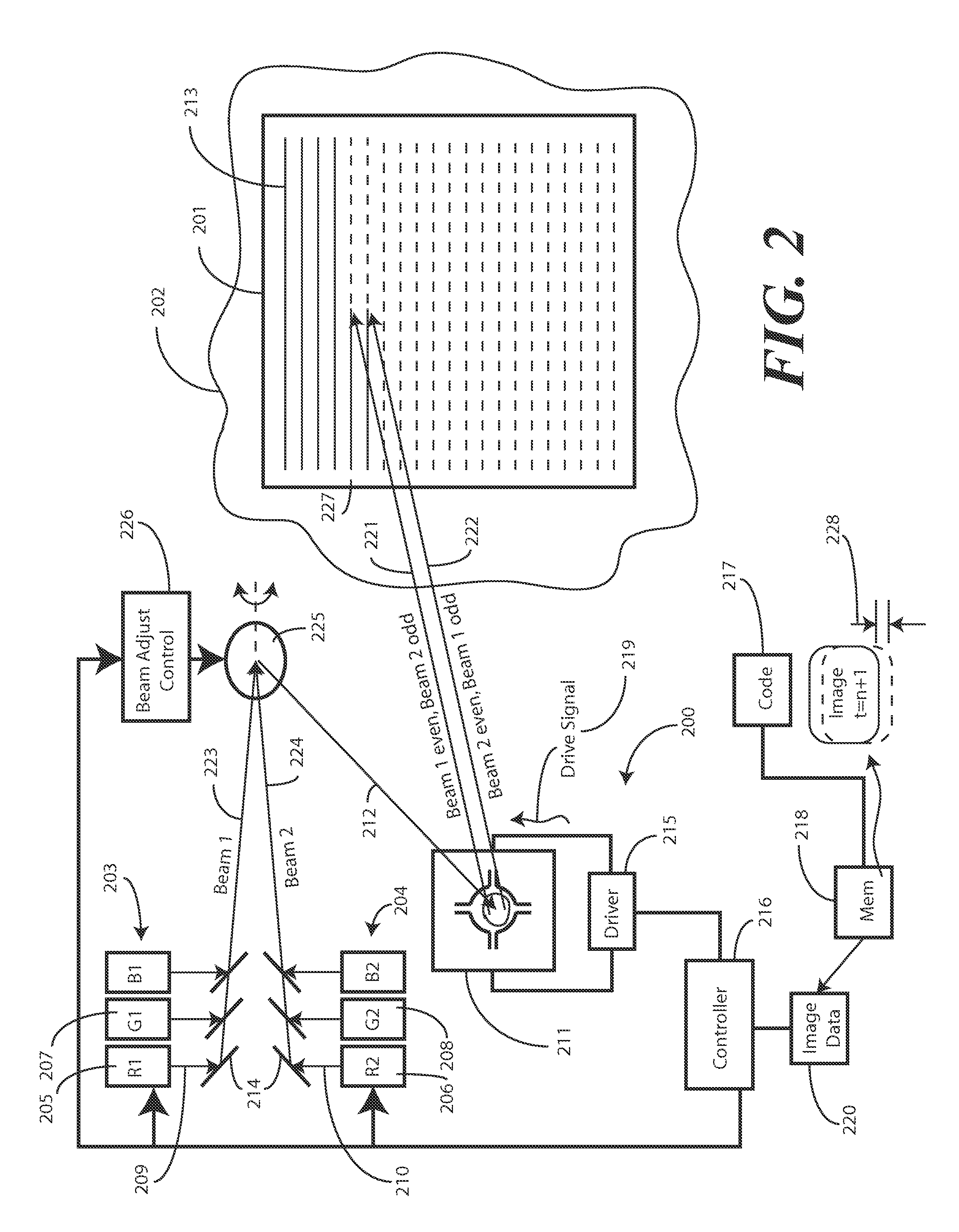
[0023]Before describing in detail embodiments that are in accordance with the present invention, it should be observed that the embodiments reside primarily in combinations of method steps and apparatus components related to an imaging system configured to reduce perceived speckle. Accordingly, the apparatus components and method steps have been represented where appropriate by conventional symbols in the drawings, showing only those specific details that are pertinent to understanding the embodiments of the present invention so as not to obscure the disclosure with details that will be readily apparent to those of ordinary skill in the art having the benefit of the description herein.

[0024]It will be appreciated that embodiments of the invention described herein may be comprised of one or more conventional processors and unique stored program instructions that control the one or more processors to implement, in conjunction with certain non-processor circuits, some, most, or all of ...


PUM


Abstract

An imaging system (200) is configured to reduce perceived speckle in images (201) produced by the imaging system. The imaging system (200) includes one or more laser source pairs (205,206), with each laser source pair being configured to produce two beams (209,210) of a color. A spatial light modulator (211) is configured to produce the images (201) with light (212) from the source pairs by scanning the light (212) in a raster pattern (213) along a projection surface (202). A beam translator (225) is configured to cause lines of successive sweeps of the raster pattern (213) to be scanned with the two beams (221,222) on an alternating basis such that a line scanned by a first of the two beams in one sweep is scanned by a second of the two beams in a sequentially subsequent sweep. Other optical elements can introduce angular diversity to further reduce speckle, such as a beam shifter (2200) and a light translation element (990).

Description

CROSS REFERENCE TO PRIOR APPLICATIONS[0001]This application is related to commonly assigned U.S. application Ser. No. ______, entitled “Laser Scanning Imaging System with Reduced Speckle,” filed concurrently herewith by the same inventors, Attorney Docket No. 09-41, which is incorporated herein by reference for all purposes.BACKGROUND[0002]1. Technical Field[0003]This invention relates generally to scanned laser projection systems, and more particularly to a scanned, laser-based system employing alternating beams to scan common lines of an image to introduce wavelength diversity to reduce speckle perceived by a viewer.[0004]2. Background Art[0005]Laser projection devices facilitate the production of brilliant images created with vibrant colors. Laser projection systems are generally brighter, sharper, and have a larger depth of focus than do conventional projection systems. Further, the advent of semiconductor lasers and laser diodes allows laser projection systems to be designed as...

Claims


Application Information

Patent Timeline
IPC IPC(8): G02B27/48G02B26/10G03B21/14
CPCG02B26/101G02B27/104H04N9/3164G02B27/48H04N9/3129G02B27/145
Inventor CHAMPION, MARKFREEMAN, MARK O.LESCURE, ALBAN N.DUELLI, MARKUS
Owner MICROVISION
Why Eureka
Try Eureka