Aerodynamic balanced wood form and/or iron form golf club

Inactive Publication Date: 2012-01-19
MELLON MILTON THOMAS
View PDF9 Cites 2 Cited by
  • Summary
  • Abstract
  • Description
  • Claims
  • Application Information

AI Technical Summary

Benefits of technology

[0009]The invention is a gulf club shaft that has a reduced width transverse to the direction of motion and a greater depth parallel to the direction of motion. This shaft cross-section differs from current elongated cone shaped shafts that are s

Problems solved by technology

Club motion during the swing is subject to aerodynamic drag; a resistance to motion that increases with increasing frontal area of head and shaft.
This aerodynamic drag dissipates energy and limits club velocity.
If the ball is struck lower than the optimum point, energy is wasted in excessive elevation and the ball falls short of the target.
If the ball is struck higher than the optimum point, the ball falls short of the target and energy is wasted by rolling on the ground that may or may not have vegetat

Method used


Image

  • Aerodynamic balanced wood form and/or iron form golf club
  • Aerodynamic balanced wood form and/or iron form golf club

Examples


Embodiment Construction

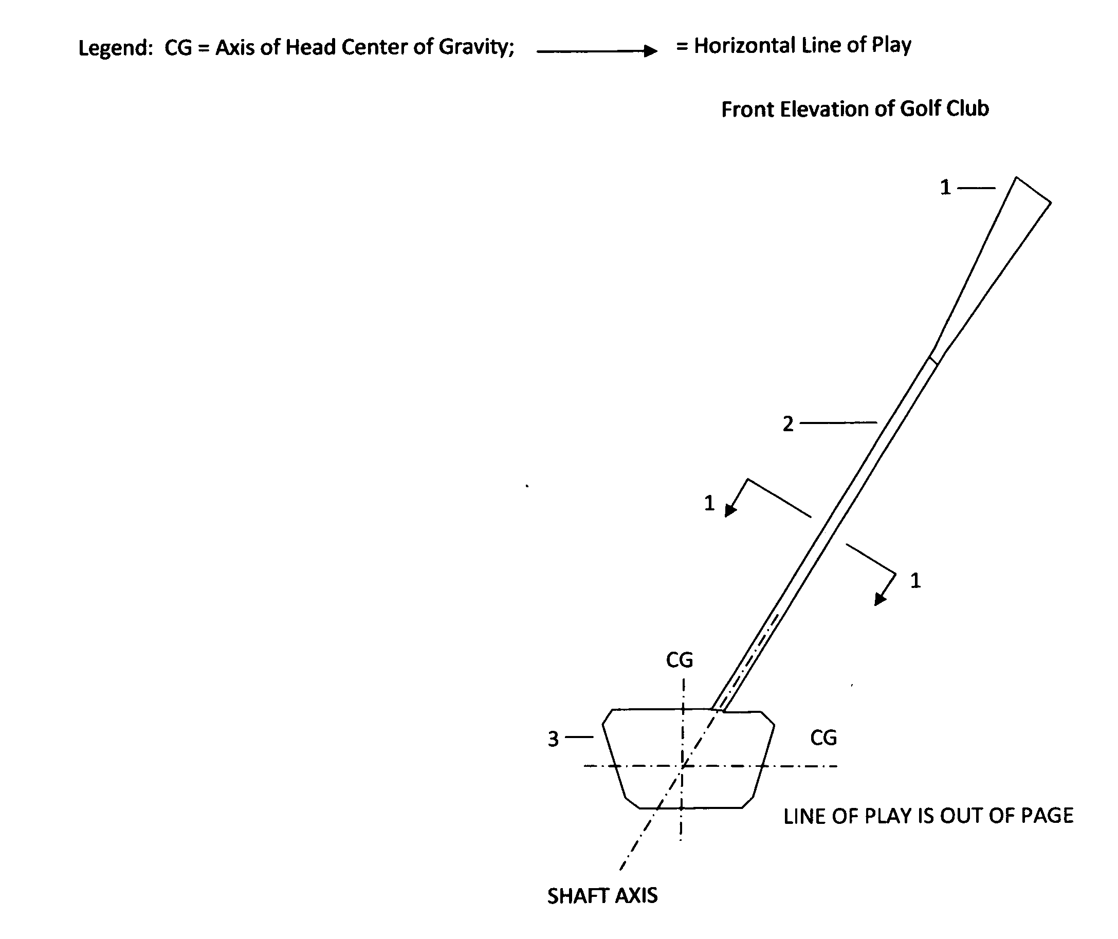
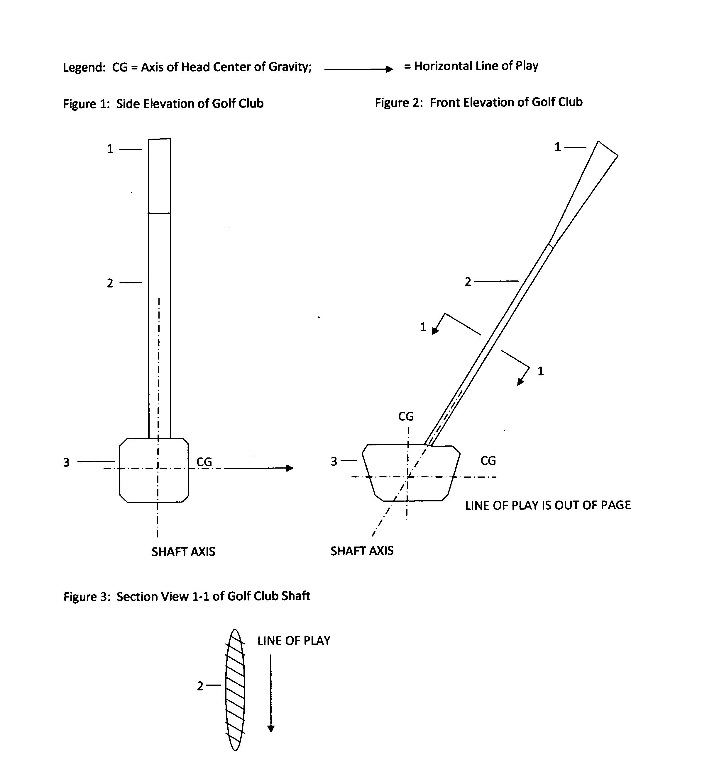
[0016]This invention is a new cross-section for a golf club shaft and a new configuration of shaft and head. This invention does not change the method of using the current golf club. Materials of construction are the same as current golf clubs. The methods of fabrication and assembly for the grip, 1 in FIG. 1 and FIG. 2, shaft, 2 in FIG. 1, FIG. 2, and FIG. 3, and head, 3 in FIG. 1 and FIG. 2, can be achieved with conventional manufacturing processes.

[0017]This invention is a gulf club shaft of typical length that has a reduced width transverse to the direction of motion and a greater depth parallel to the direction of motion. The club shaft therefore has a reduced frontal area that creates less aerodynamic drag, permits higher head velocity on impact, greater momentum transfer to the ball, higher ball velocity, and longer drives of the golf ball then current clubs that have symmetrical cone shaped shafts. The invented shaft cross-section provides higher resistance to bending away f...


PUM


Abstract

The wood or iron golf club has a reduced shaft width transverse to the direction of motion and a greater shaft depth parallel to the direction of motion, therefore, has a reduced frontal area that creates less aerodynamic drag and a higher resistance to bending opposite the direction of motion, respectively. The low drag rigid shaft allows higher head velocity, higher momentum transfer to the ball, higher ball velocity, and longer more accurate drives then current clubs with elongated cone shaped symmetrical shafts.
The wood or iron gulf club shaft-head configuration has the shaft axis intersecting the common axis of the horizontal component of the line of play and the head center of gravity. The club therefore does not create a torque about the shaft axis during the swing motion or ball impact and facilitates greater accuracy and consistency in hitting the optimum point on the ball with the optimum point on the club head.

Description

CROSS-REFERENCE TO RELATED APPLICATIONS[0001]Not applicable.STATEMENT REGARDING FEDERALLY SPONSORED RESEARCH OR DEVELOPMENT[0002]Not applicable.BACKGROUND OF THE INVENTION[0003]This specification falls under United States Patent Classification Class D21 Games, Toys, and Sports Goods, Subclass 733 Golf Club. Terminology in this specification is based on the Rules of Golf, Rule 4 Clubs, Appendix II Design of Clubs, Jan. 1, 2008, published by the United States Golf Association. The wood form and iron form of golf clubs, often called drivers, are the subject of this specification; the putter form of golf club is not a consideration in this specification. Wind effects are considered negligible in this specification. Basic parts of a golf club are defined as the grip that is held by the golfer, the shaft that is a structural member between the grip and the head, and the head that is designed to strike a golf ball.[0004]In the golfing endeavor a golfer swings a golf club and strikes a golf...

Claims


Application Information

Patent Timeline
IPC IPC(8): A63B53/00
CPCA63B53/10A63B2225/01A63B59/0014A63B60/10A63B60/06A63B60/08
Inventor MELLON, MILTON THOMAS
Owner MELLON MILTON THOMAS
Why Eureka
Try Eureka