Medical tubing stabilizer

Inactive Publication Date: 2012-01-19
HOLLIDAY BARBARA R
View PDF1 Cites 16 Cited by
  • Summary
  • Abstract
  • Description
  • Claims
  • Application Information

AI Technical Summary

Benefits of technology

[0011]The described medical tubing stabilizer is a dynamic tool that adheres to the tubing itself providing extra strong handles or anchors to prevent stitch slippage and to prevent the tubing from falling out in any situation that requires a semi or permanent drainage, or other-purpose, tubing. The device also aides in stabilizing the tubing in the wound site, and thus maximizes placement in its intended area of effect (e.g., in the body cavity, in a medical context). These stabilizing effects substantially minimize slippage of stitching holding the tubing in place to prevent the tubing from falling out or becoming dislodged or displaced, thus preventing irritation and minimizing damage to the skin around the wound site, infection, seroma, edema and morbidity in a medical context.

Problems solved by technology

However, even in critical applications, there is the risk that the tubing that has been inserted into a body location may migrate or dislodge, resulting in a lack of proper function.
In some situations, in addition to failure to provide the function for which it was inserted, the dislodged tubing may actually lacerate or otherwise damage other body elements.

Method used


Image

  • Medical tubing stabilizer
  • Medical tubing stabilizer
  • Medical tubing stabilizer

Examples


Embodiment Construction

[0017]In a preferred embodiment of the invention, the described device is manufactured as a flat piece that is folded around the tube and secured by use of two snap cap closures, thus ensuring a tight fit to the tube it is designed to secure. However, other implementations are also possible within the described principles, e.g., producing the device as an extruded tube to be slid over the tube to be secured, producing the tubing to be secured with the device as a part of it. Moreover, various closure types are possible, some of which will be described herein and others of which will become apparent to those of skill in the art upon reading this disclosure. Thus, the following describes preferred embodiments, but is not intended to limit the invention to those embodiments only.

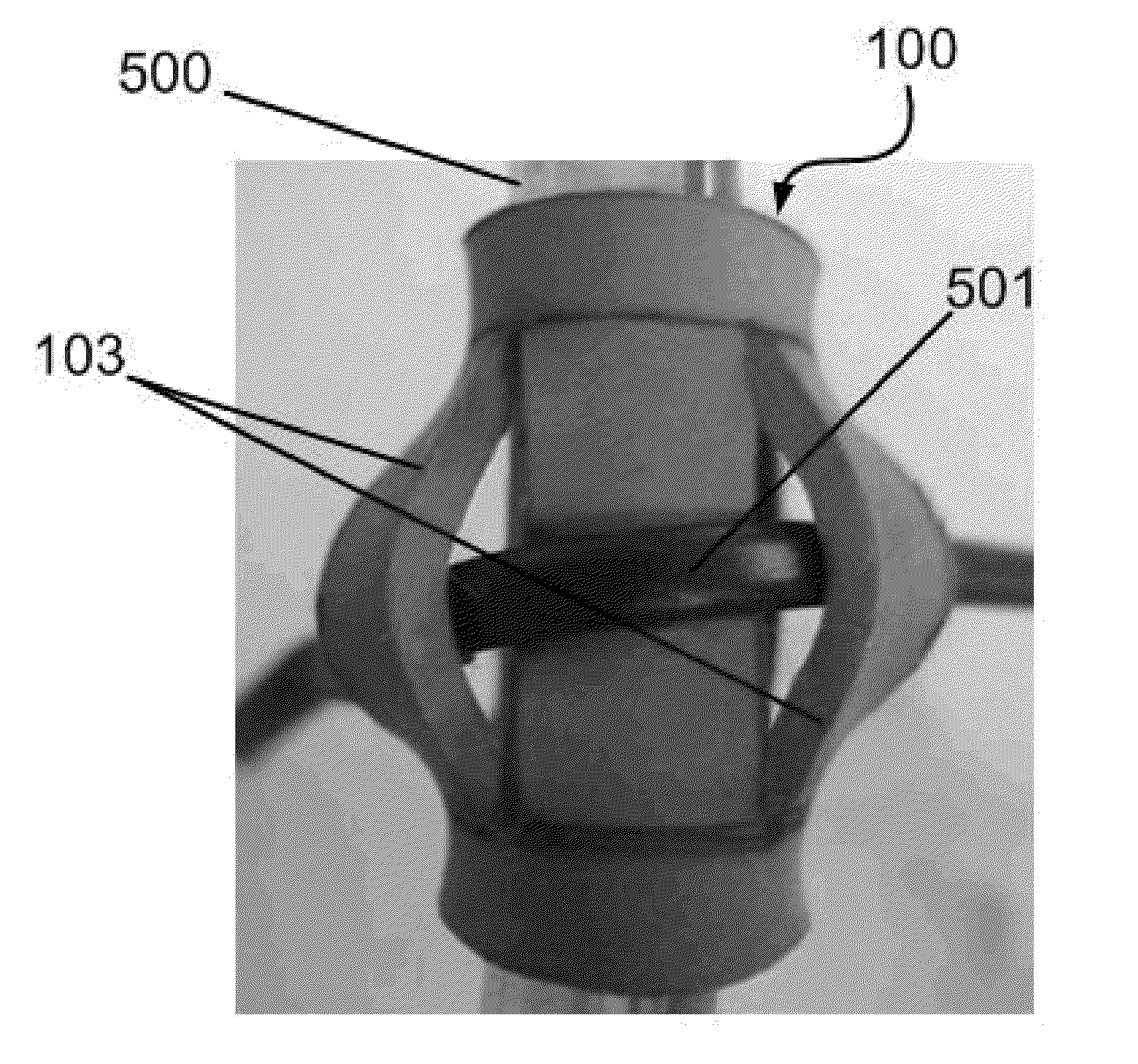
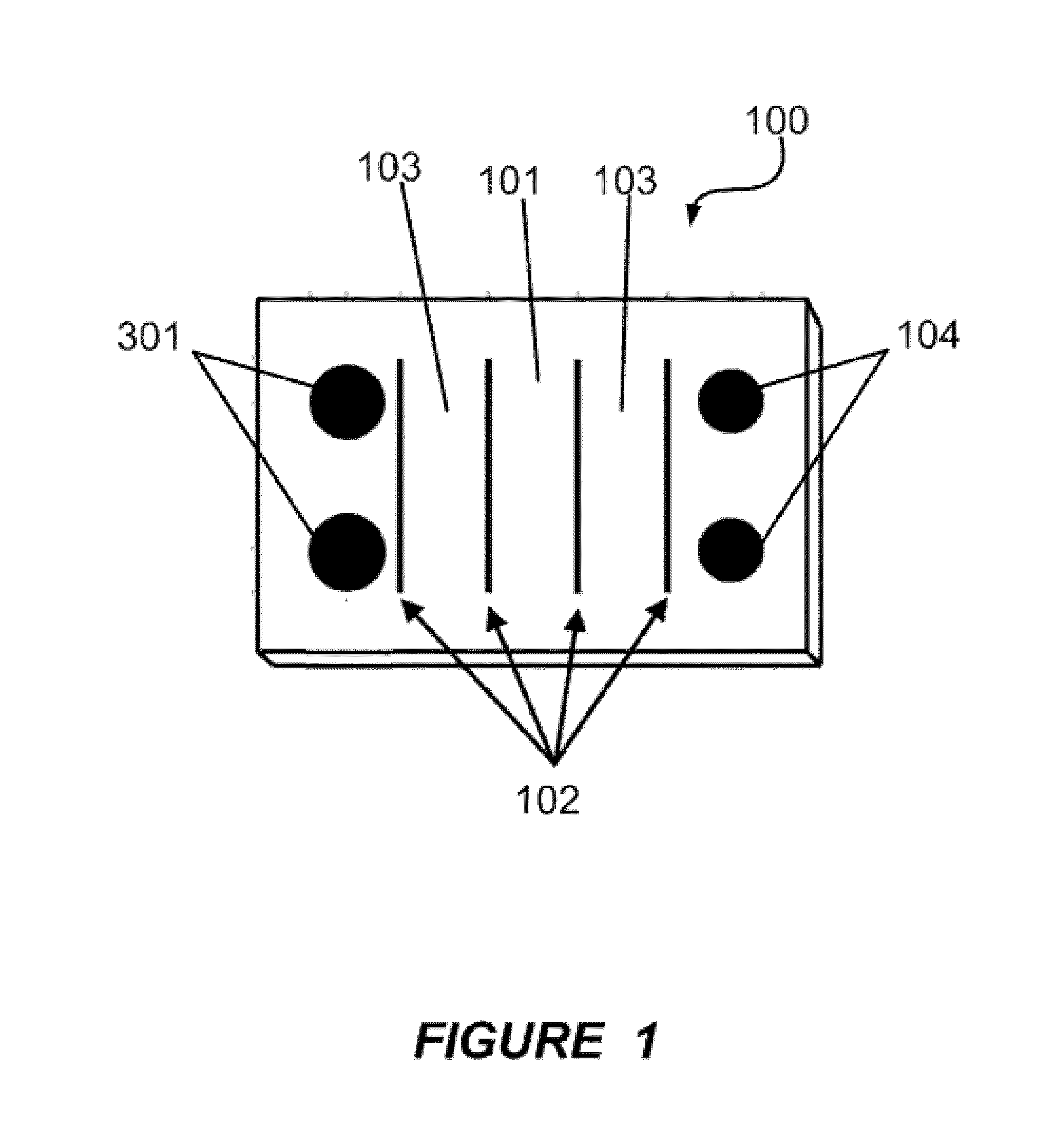
[0018]As noted above, FIG. 1 is a top and outside view of a medical tubing stabilizer in accordance with an embodiment of the invention. In the illustrated embodiment of the invention, the stabilizer 100 has a ...


PUM


Abstract

In various embodiments of the invention, a system and dynamic device are provided to create stability of tube placement in medical and other applications. The described systems and principles also apply in other environments outside of medicine and healthcare. The described medical tubing stabilizer adheres to the tubing itself providing handles or anchors to prevent stitch slippage and to prevent the tubing from falling out in any situation that requires a semi or permanent tubing placement. The device also aides in stabilizing the tubing in the wound site, and thus maximizes placement in its intended area of effect (e.g., in the body cavity, in a medical context). These stabilizing effects substantially minimize slippage of stitching holding the tubing in place to prevent the tubing from falling out or becoming dislodged or displace, thus preventing irritation and damage to the skin around the wound site, infection, seroma, edema and morbidity in a medical context.

Description

CROSS-REFERENCE TO RELATED APPLICATIONS[0001]This patent application claims the benefit of U.S. Provisional Patent Application No. 61 / 365,245 filed Jul. 16, 2011, which is herein incorporated by reference in its entirety for all that it shows, describes, and teaches, without exclusion of any portion thereof.BACKGROUND OF THE INVENTION[0002]In the medical field, it is often necessary to use tubing to provide a fluid pathway for drainage, medication, aeration, etc. However, even in critical applications, there is the risk that the tubing that has been inserted into a body location may migrate or dislodge, resulting in a lack of proper function. In some situations, in addition to failure to provide the function for which it was inserted, the dislodged tubing may actually lacerate or otherwise damage other body elements.[0003]Acute complications from tube migration or dislodgement include laceration of intercostals vessel (may require thoracotomy), lung laceration, diaphragm / abdominal c...

Claims


Application Information

Patent Timeline
IPC IPC(8): A61M39/00
CPCA61M5/1418A61M2205/04A61M25/02A61M2025/0266
Inventor HOLLIDAY, BARBARA R.
Owner HOLLIDAY BARBARA R
Why Eureka
Try Eureka