
Pressure scanner assemblies having replaceable sensor plates

a technology of sensor plates and assemblies, which is applied in the direction of liquid/fluent solid measurement, machines/engines, instruments, etc., can solve the problems of time-consuming, costly, and inability to be easily replaced by users,

Active Publication Date: 2012-01-19
KULITE SEMICON PRODS
View PDF21 Cites 12 Cited by
  • Summary
  • Abstract
  • Description
  • Claims
  • Application Information

AI Technical Summary

Problems solved by technology

This is typically done by manually entering correlation and correction coefficients into a data acquisition system, which can be time consuming.
In many embodiments, the sensor plates are built into the pressure scanner assembly and thus, cannot be easily replaced by the user.
Instead, the user must send the pressure scanner assembly back to the manufacturer to replace the necessary sensor plates or individual sensors, which can be time consuming and costly.
Therefore, if a sensor plate configured to operate under different pressure parameters is used as the replacement sensor plate, it will adversely interfere with the electronics of the overall pressure scanner assembly.

Method used


Image

  • Pressure scanner assemblies having replaceable sensor plates
  • Pressure scanner assemblies having replaceable sensor plates
  • Pressure scanner assemblies having replaceable sensor plates

Examples


Embodiment Construction

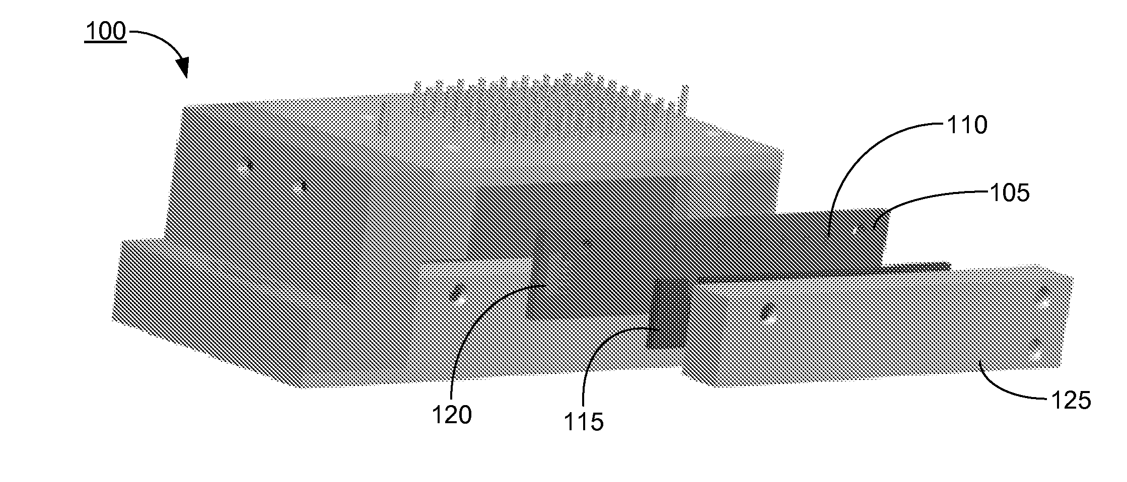
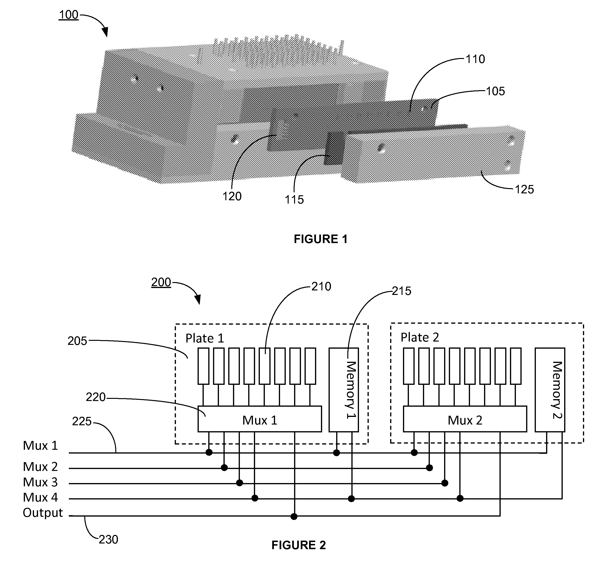
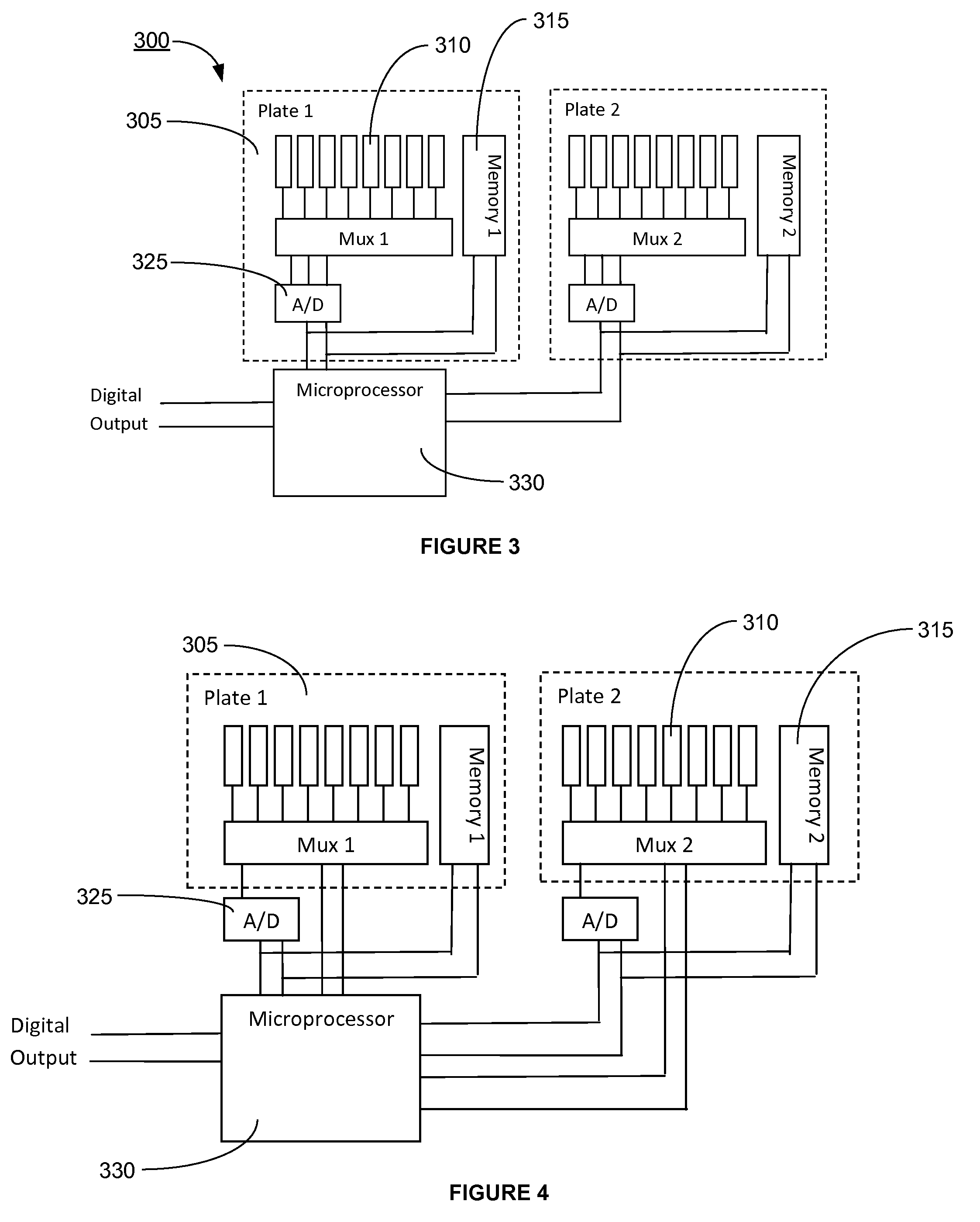
[0018]Although preferred embodiments of the invention are explained in detail, it is to be understood that other embodiments are contemplated. Accordingly, it is not intended that the invention is limited in its scope to the details of construction and arrangement of components set forth in the following description or illustrated in the drawings. The invention is capable of other embodiments and of being practiced or carried out in various ways. Also, in describing the preferred embodiments, specific terminology will be resorted to for the sake of clarity.

[0019]It must also be noted that, as used in the specification and the appended claims, the singular forms “a,”“an” and “the” include plural referents unless the context clearly dictates otherwise.

[0020]Also, in describing the preferred embodiments, terminology will be resorted to for the sake of clarity. It is intended that each term contemplates its broadest meaning as understood by those skilled in the art and includes all tech...


PUM


Abstract

A pressure scanner assembly having at least one replaceable sensor plate, wherein each of the replaceable sensor plates has at least one pressure sensor adapted to transmit a signal substantially indicative of a sensed pressure condition. A memory chip, which stores correction coefficients for each of the pressure sensor to compensate for thermal errors, may be installed on each of the replaceable sensor plates. The signals from the pressure sensors are multiplexed and may be outputted in analog or digital form. The pressure scanner assemblies described herein have sensor plates that can be interchanged with other sensor plates of the same or different pressure range without disrupting the electronic configuration of the pressure scanner assembly or having to recalibrate and / or update the memory chip installed thereon.

Description

CROSS-REFERENCE TO RELATED APPLICATIONS[0001]This application claims priority under 35 U.S.C. §119(e) to U.S. Provisional Patent Application No. 61 / 365,231, filed on Jul. 16, 2010, which is hereby incorporated by reference in its entirety as if fully set forth herein.BACKGROUND[0002]Pressure scanner assemblies are high accuracy, low-cost devices that incorporate and combine many pressure sensors (e.g., 8, 16, 32, 64, etc.) having wide pressure ranges into one small box. More specifically, the pressure sensors are housed in various sensor plates that correspondingly fit within the small box of the pressure scanner assembly. Each pressure sensor is configured to measure pressure of an applied pressure source and subsequently produce an output indicative of that pressure. This output is then transmitted via an electrical connector to a data logging system. This output can be in analog or digital form.[0003]The data from the pressure scanner assembly must then be correlated to actual pr...

Claims


Application Information

Patent Timeline
IPC IPC(8): G06F19/00
CPCG01L15/00G01L9/0052
Inventor MARTIN, RICHARDDEROSA, LOUVANDEWEERT, JOSEPH
Owner KULITE SEMICON PRODS
Learn More