Magnetic 3D Sensor Calibratable During Measurement Operation

a 3d sensor and measurement operation technology, applied in the field of hall sensors, can solve the problems of sensor operation with compensation method, sensor cannot be operated with one point measurement, and cannot measure magnetic field at one point, so as to achieve simple and uncomplicated test options, no additional hardware or time effort is required

Active Publication Date: 2012-01-19
FRAUNHOFER GESELLSCHAFT ZUR FOERDERUNG DER ANGEWANDTEN FORSCHUNG EV
View PDF1 Cites 71 Cited by
  • Summary
  • Abstract
  • Description
  • Claims
  • Application Information

AI Technical Summary

Benefits of technology

[0026]A first combination of the measurement results of the individual phases allows the extraction of a measurement component originating from the magnetic field to be measured, and in which both components originating from the calibration field and components originating from device tolerances are substantially eliminated. Further, a second combination of the measurement results of the individual measurement phases allows the extraction of a measurement component originating from the calibration field and in which components of the magnetic field to be measured are substantially eliminated.
[0027]The inventive magnetic field sensor and the inventive method have the advantage that no additional measurement phases are necessitated for calibration when using conventional compensation methods, such as the spinning current method.
[0028]An excitation line, which generates calibration field components in all spatial directions due to its geometry is powered, i.e. the calibration field is directed such that the two combinations of the measurement results from the individual measurement phases are enabled in the described way. Thus, generation and direction of the calibration field is adapted to the measurement phases of the compensation method or integrated in the same, respe...

Problems solved by technology

The arrangement for detecting the spatial magnetic field components, exemplarily illustrated in FIG. 10, has the problem that the magnetic field cannot be measured at one point, but at the respective centers of the individual sensors.
This inevitably causes a corruption, since no exact evaluation of the magnetic field is possible based on the magnetic field components of the magnetic field sensors detected at different positions.
The illustrated sensor has the problem that the same can only be calibrated by a defined externally generated magnetic field and has no individual excitat...

Method used


Image

  • Magnetic 3D Sensor Calibratable During Measurement Operation
  • Magnetic 3D Sensor Calibratable During Measurement Operation
  • Magnetic 3D Sensor Calibratable During Measurement Operation

Examples


Embodiment Construction

[0044]With regard to the following discussion, it should be considered that equal or similar functional elements in the different embodiments have the same reference numbers and are thus interchangeable in the different embodiments illustrated below.

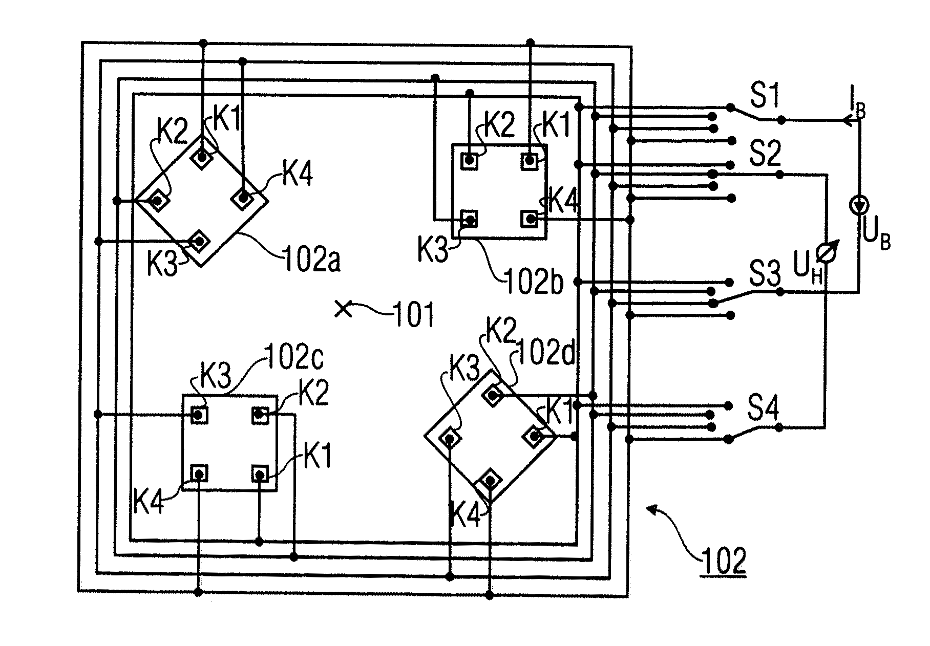
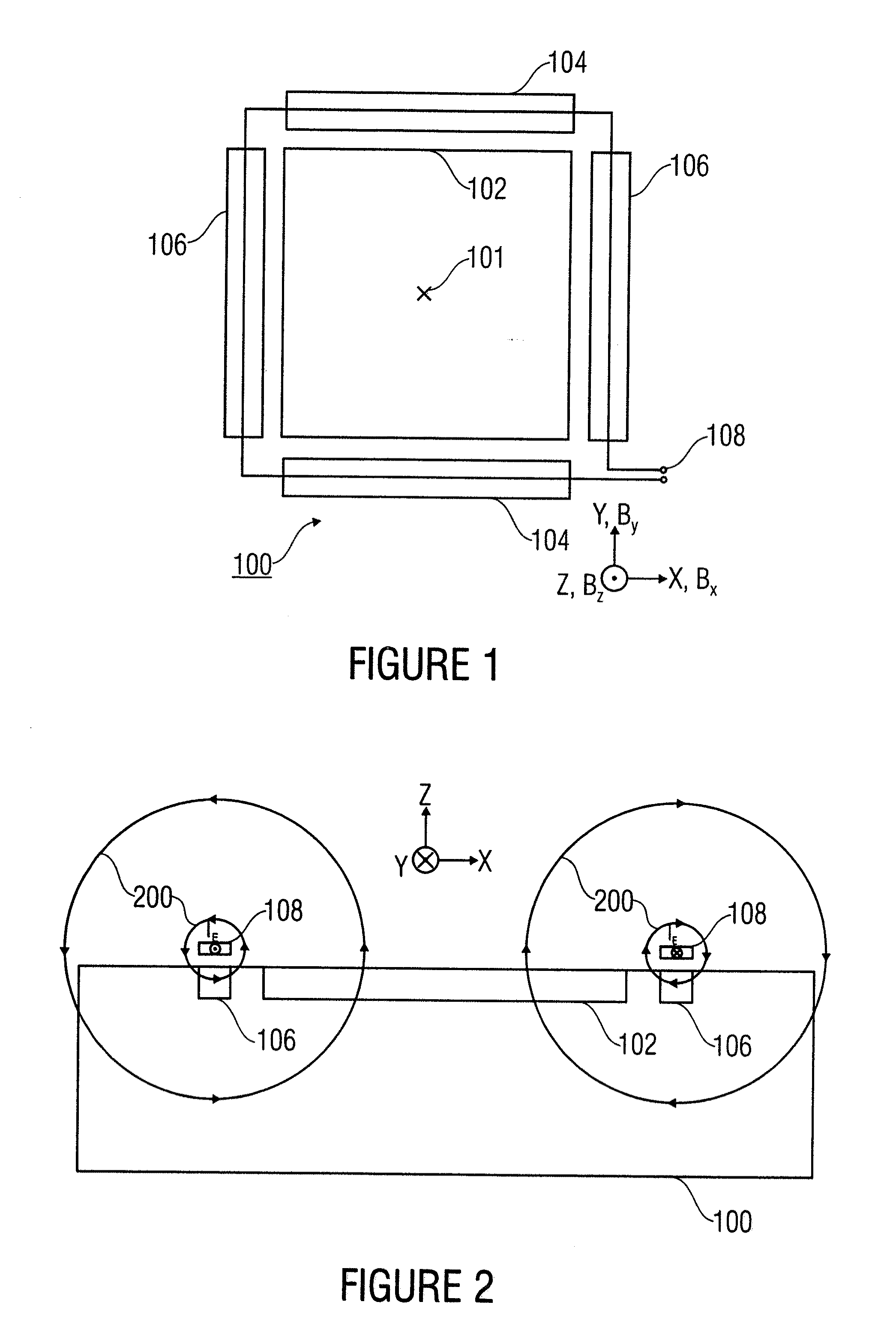
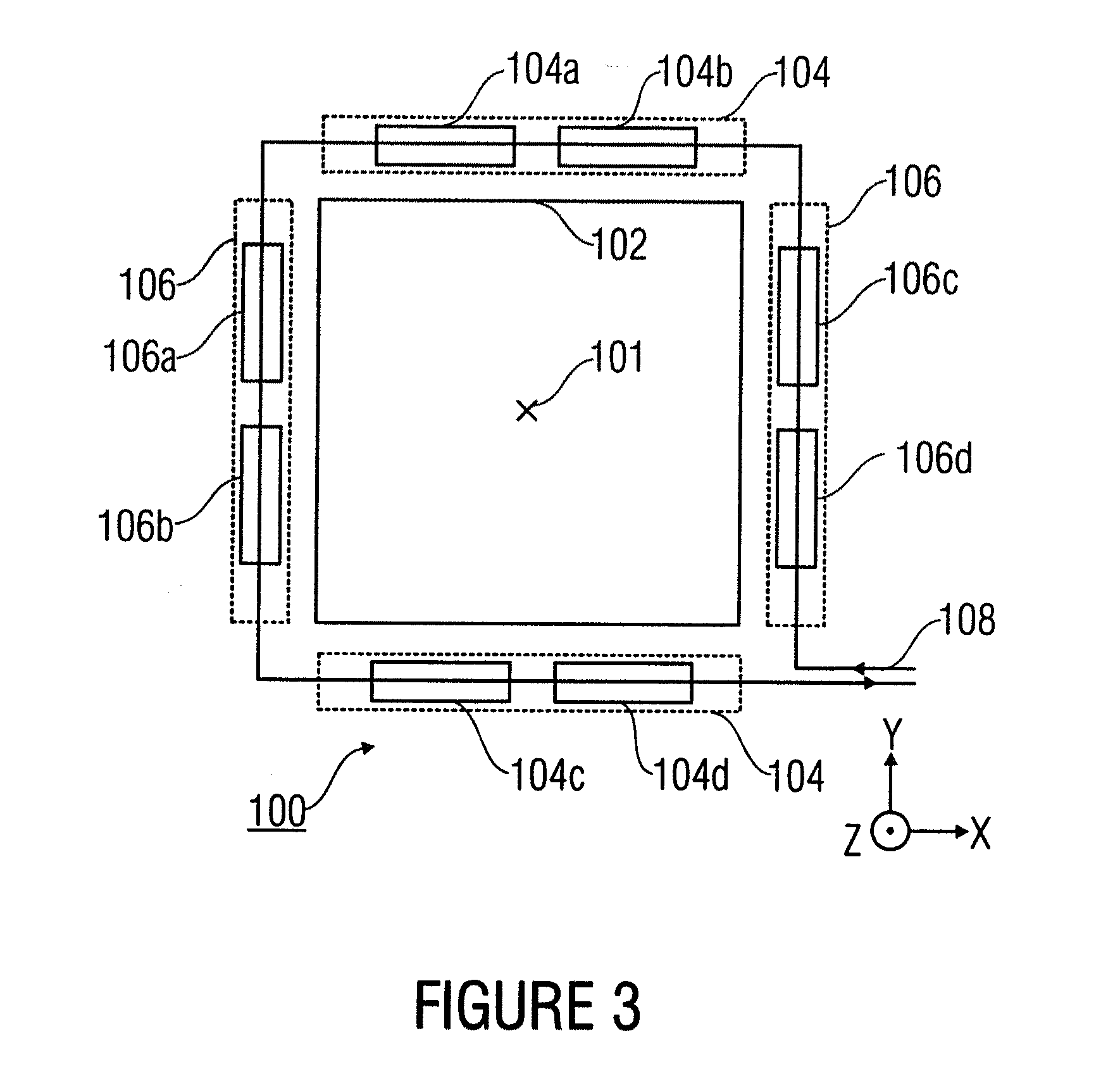
[0045]The inventive structure of a magnetic field sensor 100 calibratable during operation according to a first embodiment will be discussed with reference to FIG. 1. FIG. 1 shows an embodiment of an inventive magnetic field sensor 100 for detecting a magnetic field at a reference point 101. Further, FIG. 1 shows a first sensor element arrangement 102, a second sensor element arrangement 104, and a third sensor element arrangement 106. Further, an excitation line 108 is illustrated in FIG. 1.

[0046]The magnetic field sensor can, for example, be implemented on a substrate whose main surface runs parallel to the x-y-level of the arrangement, wherein the z-component runs perpendicular thereto. Correspondingly, the magnetic field is divided i...


PUM


Abstract

A magnetic field sensor for detecting first, second, and third spatial components of a magnetic field at a reference point includes a first sensor element arrangement for detecting the first magnetic field component having a first measurement field component and a first calibration field component with respect to a first spatial axis at a reference point, a second sensor element arrangement for detecting the second magnetic field component having a second measurement field component and a second calibration field component with respect to a second spatial axis y at the reference point and a third sensor element arrangement for detecting the third magnetic field component having a third measurement field component and a third calibration field component with respect to a third spatial axis x at the reference point. An excitation line is arranged such with respect to the three sensor element arrangements that when impressing a predetermined current into the excitation line respective predetermined calibration field components with respect to the spatial axes in the sensor element arrangements are generated.

Description

BACKGROUND OF THE INVENTION[0001]The present invention relates to Hall sensors for detecting spatial components of a magnetic field at a reference point, as well as to calibration and measurement methods used therein.[0002]Apart from measuring magnetic fields with regard to amount and direction, Hall sensor elements based on the Hall-Effect are frequently used in the art, for contactless touchless signal generators for wearless detection of the position of switches or actuators. A further possible field of application is current measurement, wherein a Hall sensor element is positioned close to a conductive trace and measures the current in the conductive trace in a contactless manner by detecting the magnetic field generated by the current in the conductive trace. In practical application, Hall sensor elements have particularly shown to be useful due to their relatively strong insensitivity against outside influences, such as contamination, etc.[0003]In the art, both the so-called h...

Claims


Application Information

Patent Timeline
IPC IPC(8): G06F19/00G01R35/00
CPCG01R15/202G01R33/0017G01R33/075G01R33/0206G01R33/07G01R33/0035
Inventor HOHE, HANS-PETERHACKNER, MICHAELSTAHL-OFFERGELD, MARKUS
Owner FRAUNHOFER GESELLSCHAFT ZUR FOERDERUNG DER ANGEWANDTEN FORSCHUNG EV
Why Eureka
Try Eureka