Tire pressure monitoring system and tire pressure sensor thereof

a technology of tire pressure monitoring and sensor, which is applied in the direction of tire measurement, vehicle components, transportation and packaging, etc., can solve the problems of increasing manufacturing costs and achieve the effect of efficient installation of tire valves

Inactive Publication Date: 2012-01-26
SEETRON
View PDF6 Cites 28 Cited by
  • Summary
  • Abstract
  • Description
  • Claims
  • Application Information

AI Technical Summary

Benefits of technology

[0011]An object of the present invention is to provide a tire pressure monitoring system and a tire pressure sensor of the system, which includes a detachable and angle-adjustable tire valve coupled to the front side of a tire pressure sensor housing, thereby freely controlling the angle of the tire valve and allowing compatible use regardless of the shape or size of wheels of cars and commercial vehicles.
[0028]Another object of the present invention is to provide a tire pressure monitoring system including: a tire pressure sensor housing installed on a side portion of a wheel to sense air pressure of a tire; an angle-adjustable tire valve coupled to a surface of the tire pressure sensor housing, having an end exposed out of the wheel through a wheel valve hole, and including a male screw part on a middle outer surface; a rubber grommet disposed on an inner surface corresponding to the wheel valve hole to prevent air from leaking out of the tire; a washer fitted on the tire valve to support the rubber grommet; a fastening nut coupled to the male screw part of the tire valve; and a receiver receiving a wireless signal denoting an air pressure state of the tire, from the tire pressure sensor housing.

Problems solved by technology

This is because a vehicle driven at high speed with air pressure of a tire being decreased by 25% or greater may cause an accident.
In other words, since a tire pressure sensor housing is integrally formed with a tire valve to fix the angle of the tire valve, TPSs should be manufactured differently according to valve hole sizes and wheel sizes, or wheel designs, thereby increasing manufacturing costs thereof.

Method used


Image

  • Tire pressure monitoring system and tire pressure sensor thereof
  • Tire pressure monitoring system and tire pressure sensor thereof
  • Tire pressure monitoring system and tire pressure sensor thereof

Examples


Embodiment Construction

[0050]Reference will now be made in detail to the preferred embodiments of the present invention, examples of which are illustrated in the accompanying drawings. Wherever possible, the same reference numbers will be used throughout the drawings to refer to the same or like parts.

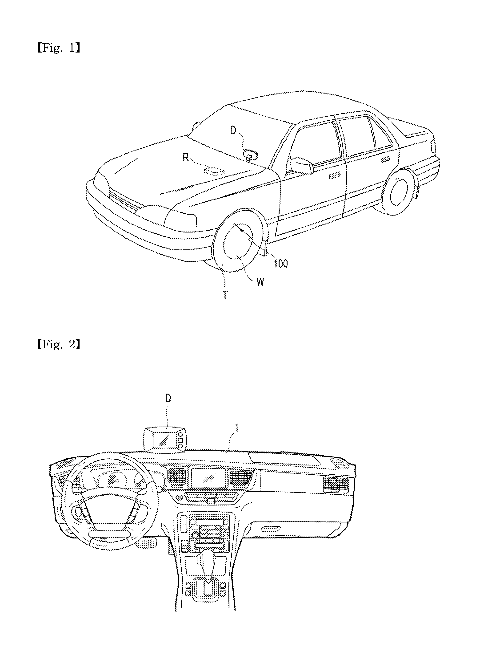
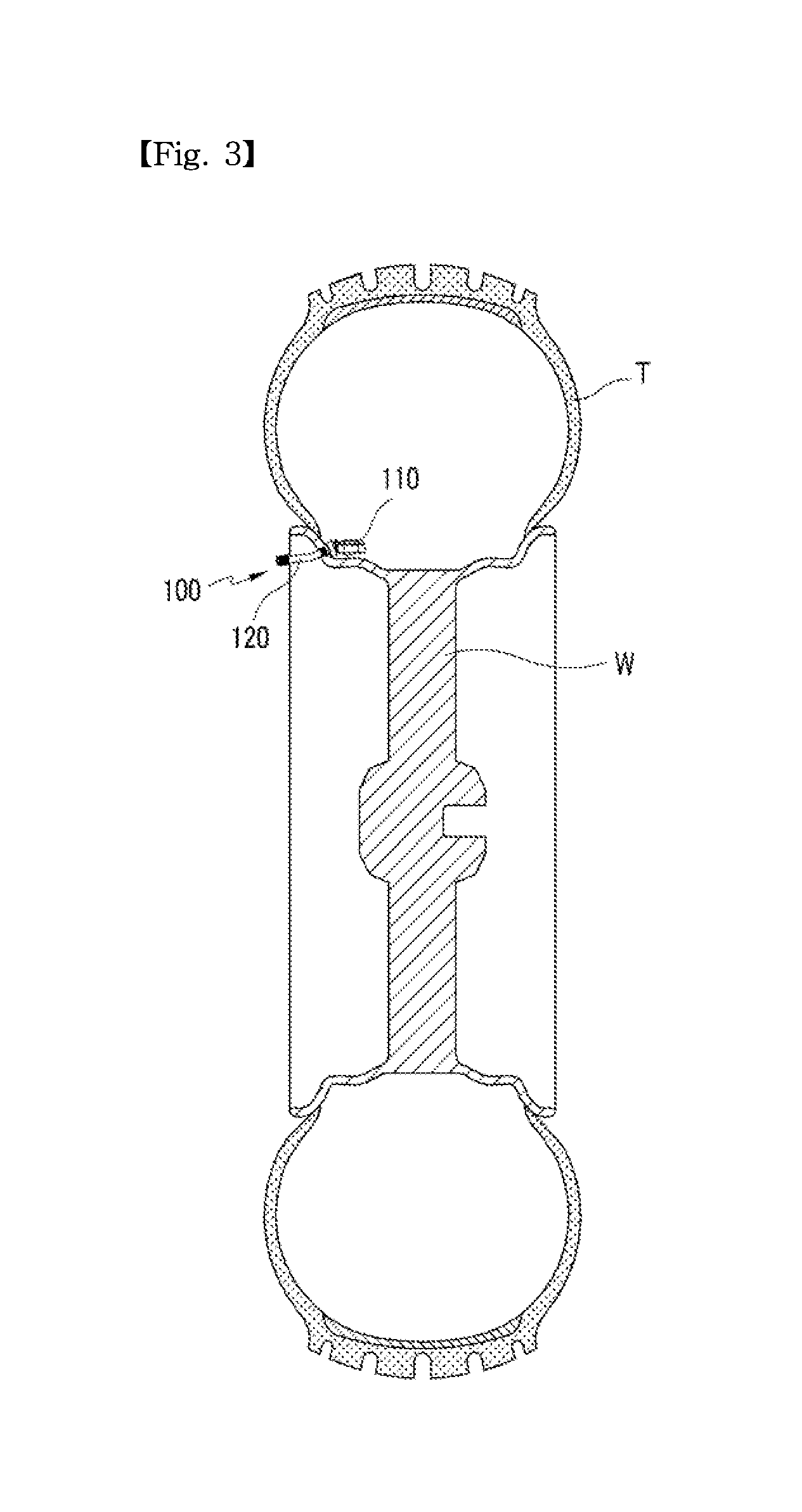
[0051]FIG. 1 is perspective view illustrating a tire pressure monitoring system (TPMS) according to an embodiment of the present invention. FIG. 2 is a schematic view illustrating an installation state of a display of FIG. 1. FIG. 3 is a cross-sectional view illustrating an installation state of a tire pressure sensor (TPS) of the tire pressure monitoring system of FIG. 1.

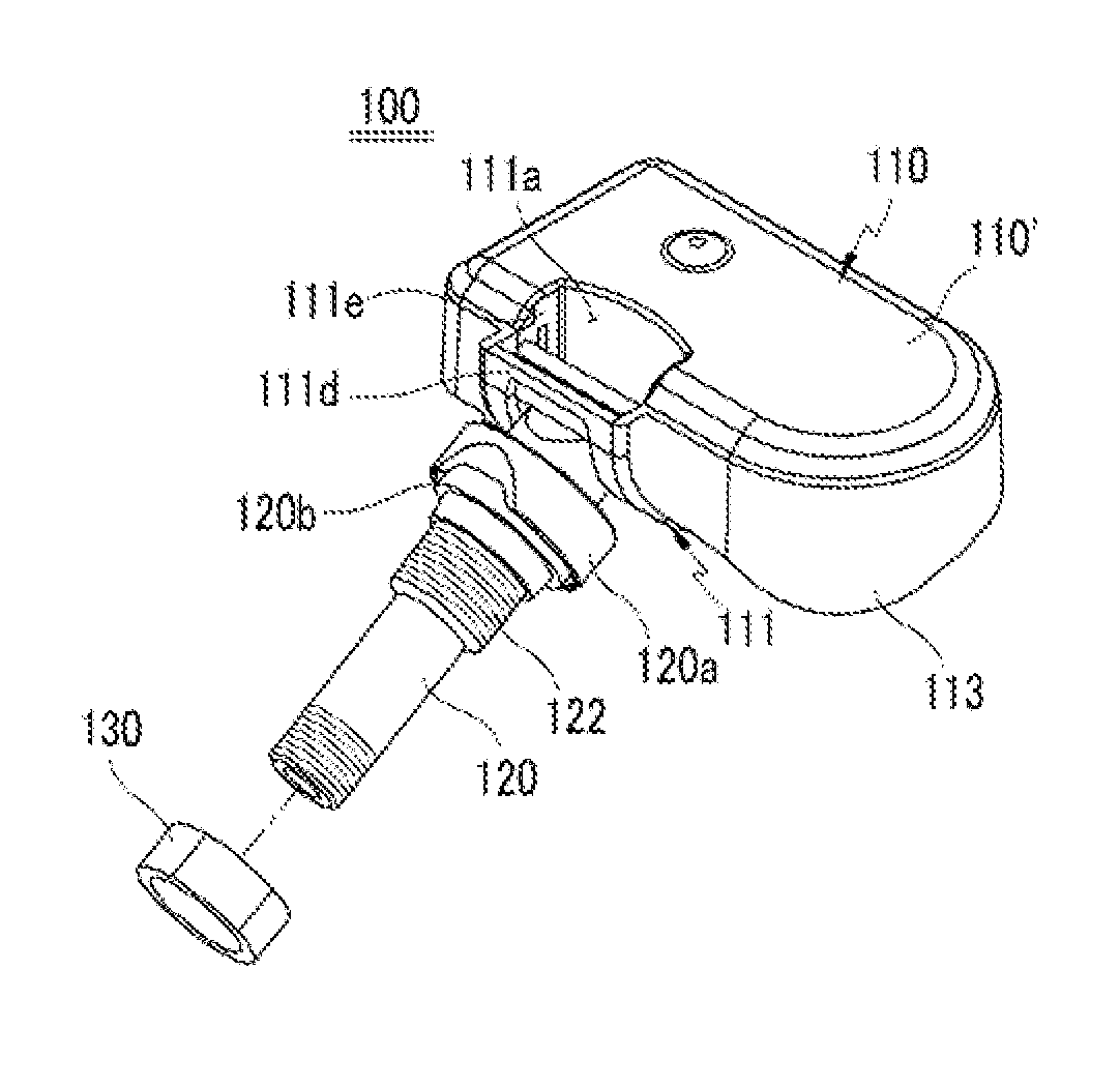
[0052]Referring to FIGS. 1 to 3, a tire pressure monitoring system according to the current embodiment includes: a tire pressure sensor housing 110 installed on a side portion of a wheel W to sense air pressure of a tire T; an angle-adjustable tire valve 120 coupled to the tire pressure sensor housing 110, having an end exposed out of the w...


PUM


Abstract

Provided is a tire pressure sensor (TPS) of a tire pressure monitoring system (TPMS). The TPS includes a detachable and angle-adjustable tire valve coupled to the front side of a tire pressure sensor housing. A holder bracket having a tire valve insertion hole is at the front side, and an insertion head inserted into the valve insertion hole is at an end of the tire valve. Accordingly, the angle of the tire valve is freely controlled, allowing compatible use regardless of the shape or size of wheels of cars and commercial vehicles. Thus, manufacturing costs can be greatly reduced, thereby obtaining superior competitiveness over competitors' products. Furthermore, air leakage through a wheel valve hole can be effectively prevented against high speed rotation and inertia motion caused by the high speed rotation during the driving of a vehicle.

Description

BACKGROUND OF THE INVENTION[0001]1. Field of the Invention[0002]The present invention relates to a tire pressure monitoring system, and more particularly, to a tire pressure monitoring system and a tire pressure sensor of the system wherein the angle of a tire valve from a tire pressure sensor housing is freely controlled, allowing compatible use regardless of the shape or size of wheels of cars and commercial vehicles.[0003]2. Description of the Related Art[0004]Vehicle manufacturers are required to install a tire air pressure alarming device on a vehicle under FMVSS 138 of NHTSA (National Highway Traffic Safety Administration).[0005]A tire air pressure alarming device installed on a vehicle may also be called a tire pressure monitoring system (TPMS) that includes a tire pressure sensor (TPS) installed on each tire of a vehicle and having its own ID. A transmitter constituting a wireless apparatus transmits radio waves to the TPS to read the ID of the TPS, and a value corresponding...

Claims


Application Information

Patent Timeline
Patent Type & Authority Applications(United States)
IPC IPC(8): B60C23/04
CPCB60C29/064B60C23/0494B60C23/04B60C23/02B60C23/00
Inventor UH, SUNG-SUNKIM, YONG-JOONJANG, YOUNG-MAN
Owner SEETRON
Why Eureka
Try Eureka