Dairy harvesting facility with milk line protection system and methods

a protection system and milk line technology, applied in the field of dairy harvesting facilities, can solve the problems of milking system being a possible source of contamination, waste of valuable time, and affecting the quality of milking,

Active Publication Date: 2012-01-26
GEA FARM TECH
View PDF3 Cites 30 Cited by
  • Summary
  • Abstract
  • Description
  • Claims
  • Application Information

AI Technical Summary

Benefits of technology

[0032]During milking, the valves are closed and the vent is open. Both valves prevent sanitizer fluids from flowing into the inflation. Nonetheless, even the best valves can be subject to leakage over time due to wear and differential pressures on opposite sides of the valve, for example. In the present invention, vacuum or other pressure differentials cannot draw sanitizing fluids through the valves and into the inflation because the vent provides air at atmospheric pressure between the valves to obviate the effect of the vacuum.
[0033]The downstream valve may suffer from some leakage, but the vacuum or pressure differential from the inflation cannot draw any leakage through the upstream valve (closest to the sanitizer source) because the intermediate vent causes pressure in the sanitizer conduit to be essentially at atmospheric pressure regardless of influences from the milk system vacuum. As stated above, this arrangement is sometimes referred to as “block-bleed-block” because two valves block the conduit and the intermediate vent bleeds the conduit of vacuum and other pressure differentials. Thus, the milking system is protected from any valve leakage of sanitizer fluids.
[0042]System advantages for the preparation procedures of the present invention include: teat cups remain closed throughout cleaning and milking, reducing possibility of contamination (no cross-contamination of teats, nothing can splash onto teats after cleaning, nothing can fall into milking cups after cleaning—no debris from cow's udder or belly, fly free, and no dirty air, no teat is milked unless it is cleaned first); cleaning cycle removes debris and bacteria from teats and milk line—a block-bleed-block valve configuration separates cleaning cycle solutions from the milk line; unique cluster keeps milking cups suspended minimizing risk of floor contact; all fluid flows down and away from the cow; the default path of milk flow is always to the drain before diverting good milk to the receiver; barn layout creates a clear division of two areas; special needs cows can easily be housed and milked separately; easily able to attach cows manually; and multi-box system allows shortest milk transfer system possible.

Problems solved by technology

Attaching two separate units to the animals with the teats exposed for a brief interval in between, wastes valuable time and risks the teats becoming dirty again.
This system is efficient and effective, but attaching a preparation system to a milking system may be a possible source of contamination because vacuum in the milking system could draw sanitizer, water or dirt from the cleaning system into the milking system.
Moreover, dairy pipeline washing fluids and contaminated milk must not be allowed to enter milk lines that transport milk to centralized chillers and storage tanks unless the milk lines themselves are to be cleaned.
Nonetheless, a four-way valve can be insufficient to prevent cleaning fluids and contaminated milk from entering the dairy milk collecting system because vacuum in the milk lines (used to draw milk to a central storage location) results in the milk line having a different pressure than the wash lines, and the wash lines are subjected to various pressures before and after a wash cycle.
Differential pressure and vacuum applied on opposite sides of a four-way valve are likely to cause seepage and leaking of milk and / or cleaning fluids past seals in the four-way valve.
Thus, the competing pressures in the various lines attached to the four-way valve could eventually cause valve failure and milk line contamination to some degree.
This problem is well known in dairies that use clean-in-place (“CIP”) wash systems.
The block-bleed-block arrangement is not new to the dairy industry, but implementing a block-bleed-block system is not always possible, convenient or practical.
Expense for building and maintaining these systems can be prohibitive, so when space does not permit a block-bleed-block arrangement, some milking systems are designed to segregate wash and milk lines in other ways.
Requiring an operator to be involved is further complicated in robotic systems because milking machines are washed only when necessary, and not on a regular basis that would be conducive to operator scheduling.
Involving an operator would likely slow down the milking process for the dairy as a whole, and would at least partially defeat the point of a robotic milking system.

Method used


Image

  • Dairy harvesting facility with milk line protection system and methods
  • Dairy harvesting facility with milk line protection system and methods
  • Dairy harvesting facility with milk line protection system and methods

Examples


Embodiment Construction

[0079]To the extent reasonable and practical, the same identification numeral will be used to identify the same or similar feature in each of the figures.

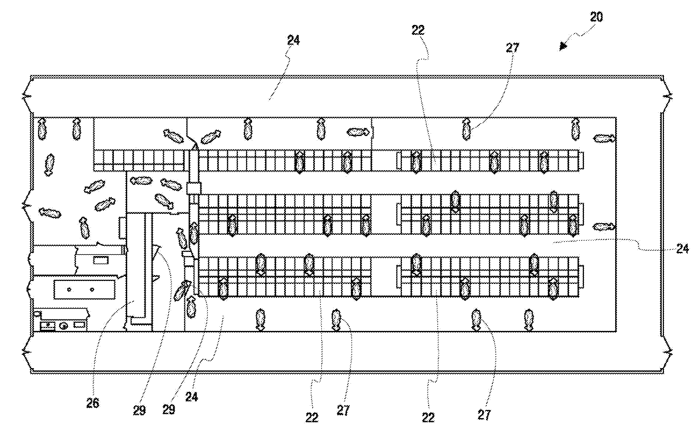
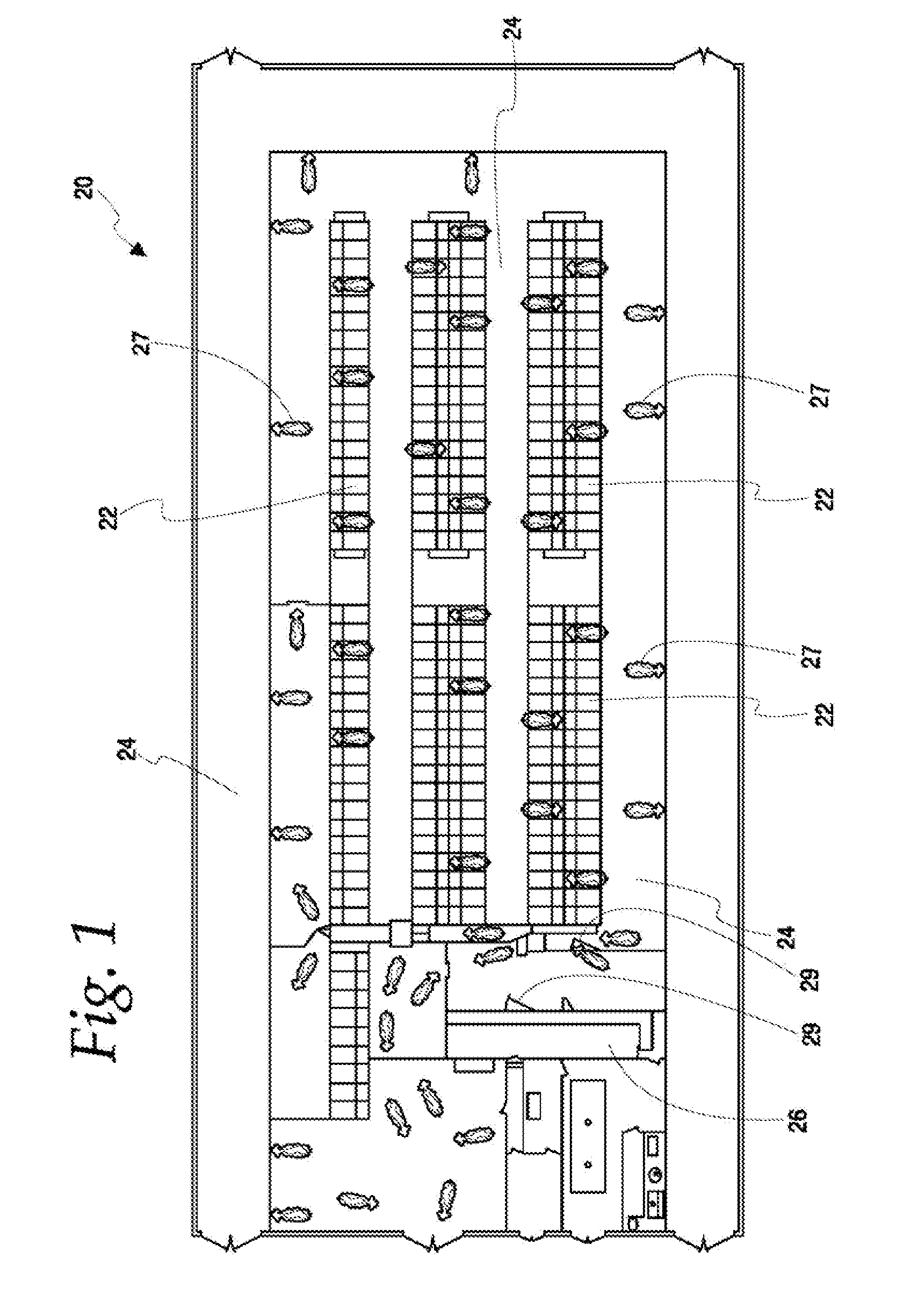
[0080]Illustrated generally in FIG. 1 is a dairy harvesting facility 20 having stalls 22, alleys 24, and milking stalls 26. Dairy animals 27 move through the dairy harvesting facility 20 to feed, rest, and be milked in the milking stalls 26. Control gates 29 can be used to sort cows or to prevent them from entering a particular area. Preferably, an animal identification system is used to identify cows for sorting and correlating to milk, illness, and other purposes.

[0081]The milking stalls 26 can be of any shape or arrangement, and be stationary or rotatable. Animals can be allowed to enter the milking stalls at will or be controlled by gates 29 that are selective based on the animal's history of milking or health considerations. Animals can also be moved into the milking stalls 26 by an operator.

[0082]In a preferred embodiment of ...


PUM


Abstract

Apparatus and methods for a dairy harvesting facility including valves and valve assemblies that prevent contaminants from reaching a central milk collection system.

Description

[0001]This application claims the benefit of Provisional Application No. 61 / 338,630 filed Feb. 22, 2010, the disclosure of which is incorporated by reference herein.FIELD AND BACKGROUND OF THE INVENTION[0002]This invention relates to apparatus and methods for milking dairy animals and collecting milk, and more particularly to a dairy harvesting facility with apparatus and methods for protecting milk collecting lines and systems from various types of cleaning fluids and contaminated milk.[0003]In dairy milking systems, sanitary conditions must be maintained to the extent possible. Dirt can enter a dairy milk system through the teat cup and liner (“inflation”) that are attached to an animal to extract milk. Vacuum is used to milk the animal and draw milk into the hoses, lines and storage tank system in the dairy. Any dirt on the animal's teats can be drawn into the system by this vacuum.[0004]To minimize dirt in the dairy milking system, a dairy animal is prepared for milking by an op...

Claims


Application Information

Patent Timeline
Patent Type & Authority Applications(United States)
IPC IPC(8): A01J7/02A01J5/007B08B9/00A01J5/00
CPCA01J7/022A01J7/04A01J5/007
Inventor TORGERSON, KEVIN L.SELLNER, DUANE F.
Owner GEA FARM TECH
Why Eureka
Try Eureka