
Recording device

a recording device and recording medium technology, applied in the direction of printing, other printing apparatus, etc., can solve the problems of excessive load on the recording medium, interference with the device, and flexing of the recording medium, so as to achieve the effect of higher accuracy

Active Publication Date: 2012-01-26
SEIKO EPSON CORP
View PDF2 Cites 12 Cited by
  • Summary
  • Abstract
  • Description
  • Claims
  • Application Information

AI Technical Summary

Benefits of technology

[0008]The present invention was contrived in view of the foregoing problems of the prior art, and an object thereof is to provide a recording device that can reduce interference with the recording processing part in the case that an abnormality has occurred in the conveyance system of the recording medium.
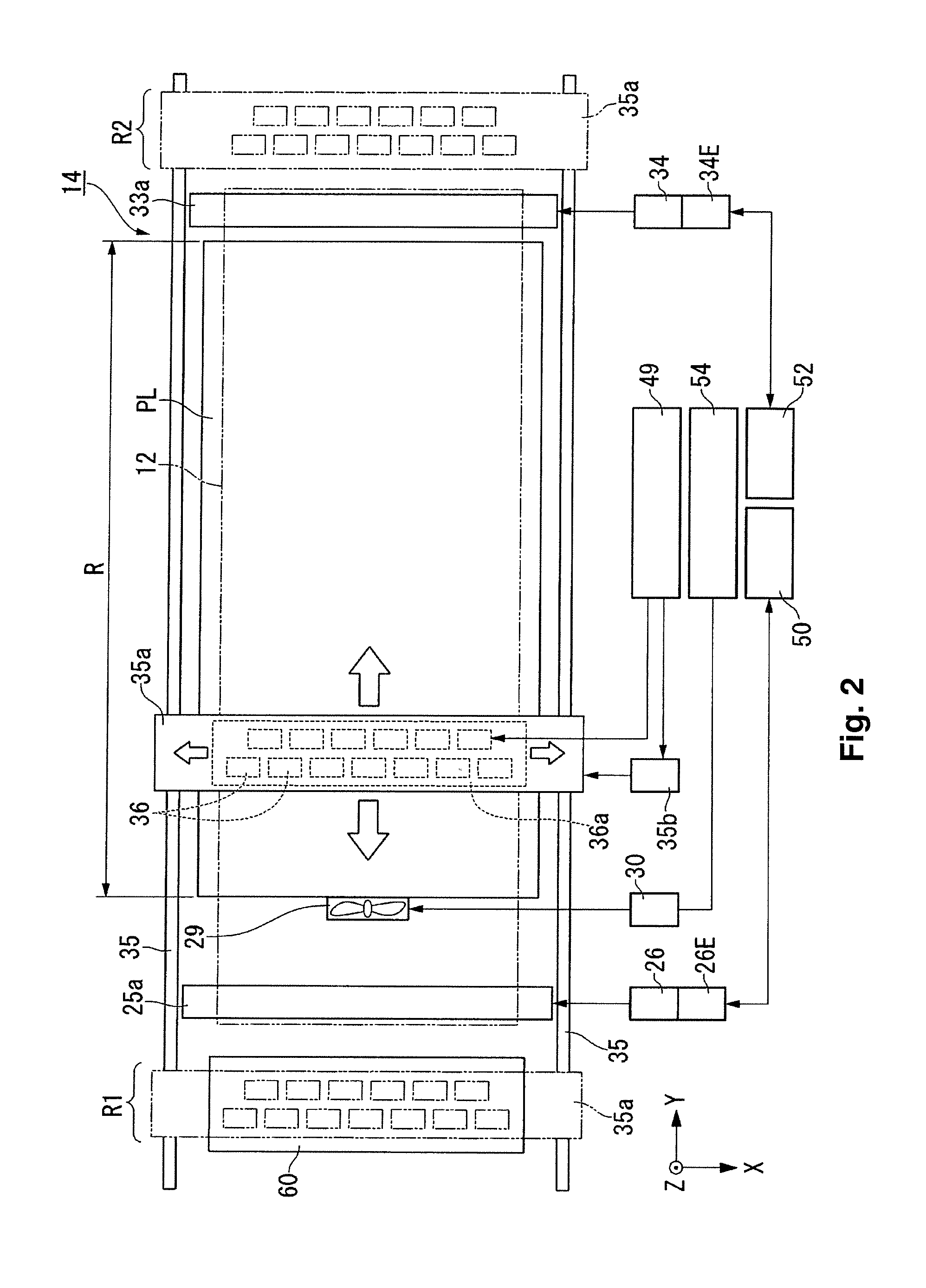
[0010]In accordance with the aspect described above, since the recording processing part is retracted to an area outside of the medium-supporting part in the case that a predetermined abnormality has occurred in the medium conveyance system, contact between the recording processing part and the recording medium can be made less liable to occur even when the recording medium flexes due to an abnormality. It is thereby possible to prevent defects from extending to the recording processing part due to an abnormality of the medium conveyance system. Since the retract operation is carried out by moving the recording processing part in the unchanged forward direction of movement in the recording process when the recording processing part is to be retracted, the recording processing part can be rapidly retracted and it is possible to prevent a load being applied to the recording processing part conveyance system due to a sudden change of direction of the recording processing part. Alternatively, the recording processing part can be retracted to an area outside of the medium-supporting part by moving a shorter distance because the recording processing part is retracted to an area outside of the medium-supporting part so as to face in the direction of the edge of the medium-supporting part that is shorter in distance from the recording processing part at a time at which the abnormality has occurred, regardless of the movement direction of the recording processing part at the time at which the abnormality has occurred.
[0014]The first type of abnormality is an abnormality of the power supply system or the drive system that is detected as an abnormality of the electric current value of the drive motor, and the possibility that the recording medium will be made to flex or the like is high. On the other hand, the second type of abnormality is an abnormality detected in the case that an excessive load has been applied to the drive motor, and will not immediately result in a defect in the operation of the drive motor when detected. In accordance with the configuration described above, a recording device is obtained in which the recording processing part is less likely to be damaged and product waste is reduced because the recording processing part is retracted in the case that the first type of abnormality has been detected, and the recording process is continued in the case that the second type of abnormality has been detected.
[0016]It is thereby possible to prevent misdetection of errors caused by a phenomenon in which the maximum electric current value is reduced when the rotational speed of the motor is high.
[0018]An excessive load of the drive motor can thereby be detected with relatively higher accuracy than by simple computational processing. Initial settings can be established in a simple manner because the electric current calorimetric coefficient α and the heat discharge constant β can be readily set by experimentation.

Problems solved by technology

When an abnormality occurs in the conveyance system, a recording medium undergoes an excessive load or the recording medium flexes and interferes with the device in the case that a long recording medium such as continuous paper is used.
In the particular case that the recording medium flexes on a platen, the recording medium may come into contact with the inkjet head and cause a defect in the inkjet head or the head conveyance system.
However, this method has a drawback in that the product in process is wasted.
The first type of abnormality is an abnormality of the power supply system or the drive system that is detected as an abnormality of the electric current value of the drive motor, and the possibility that the recording medium will be made to flex or the like is high.
On the other hand, the second type of abnormality is an abnormality detected in the case that an excessive load has been applied to the drive motor, and will not immediately result in a defect in the operation of the drive motor when detected.

Method used


Image

  • Recording device
  • Recording device
  • Recording device

Examples


Embodiment Construction

[0032]Embodiments of the recording device are described hereinbelow with reference to the drawings.

[0033]The scope of the present invention is not limited to the embodiments below, and modifications can be made as desired within the scope of the technical concepts of the present invention. The scale, number, and other parameters in the actual structure and each structure may be different in the drawings in order to facilitate understanding of each configuration.

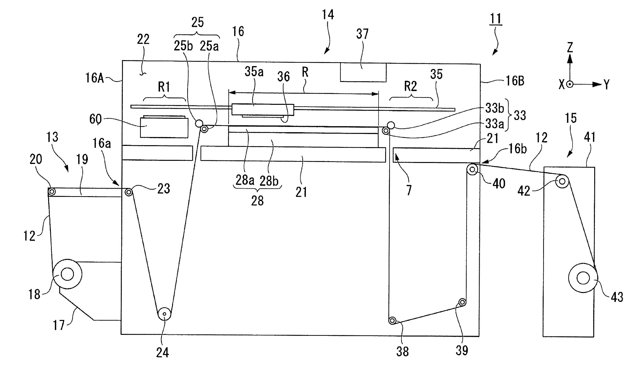
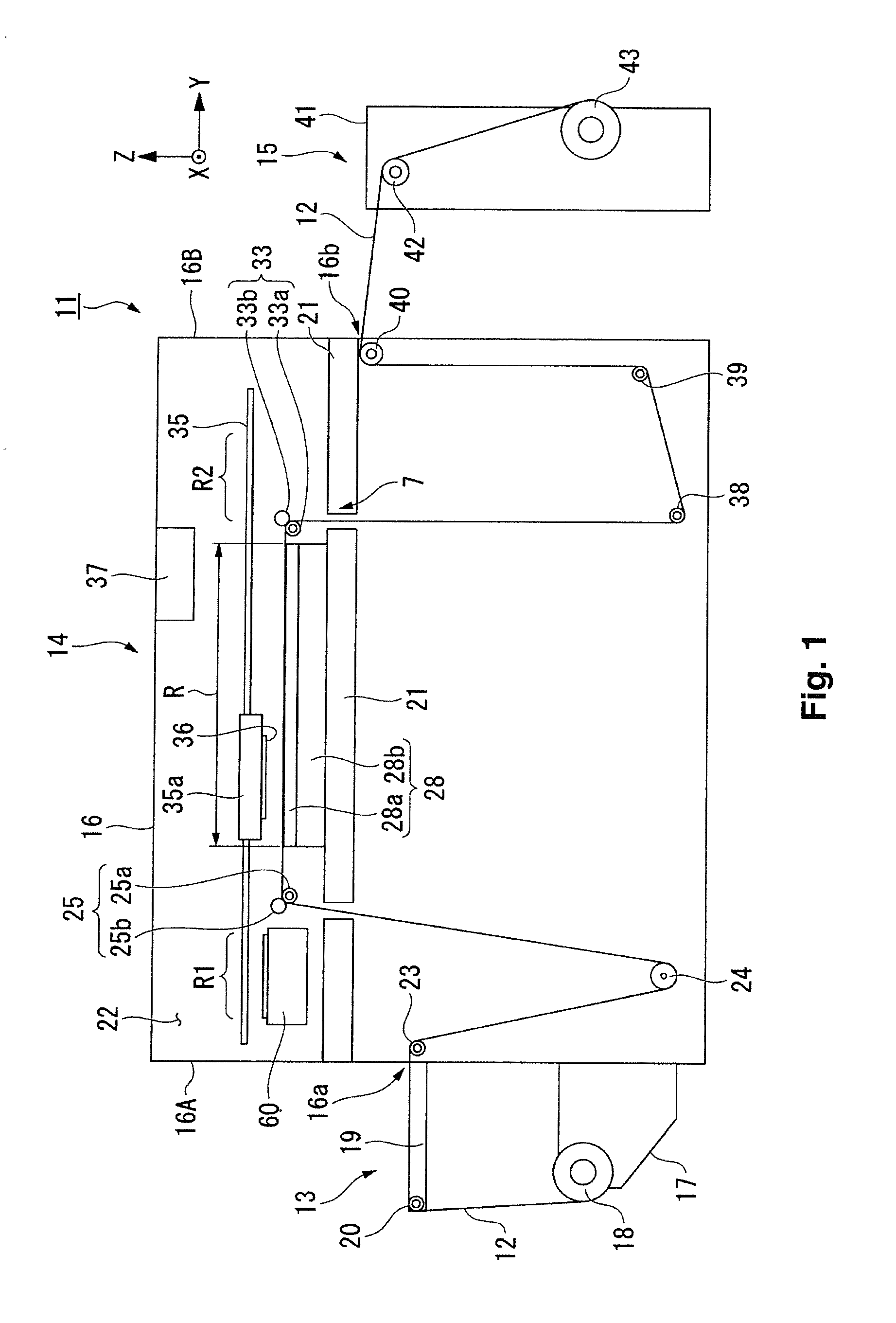
[0034]FIG. 1 is a view showing the printer of the present embodiment. FIG. 2 is a plan view of the print area used for printing in the printer. FIG. 3 is a lateral sectional view of the platen.

[0035]A printer 11 (recording device) uses as the print method an inkjet method for jetting a fluid from a plurality of recording heads (fluid jet head) onto a continuous paper 12, carries out a printing process while sequentially feeding out the long continuous paper (recording medium) 12 wound in the form of a roll, and then winds the...


PUM


Abstract

A recording device has a medium-supporting part that supports a long recording medium, a recording processing part that performs recording process on the recording medium supported by the medium-supporting part, a recording processing part conveyance system that moves the recording processing part, a medium conveyance system that includes a first drive roller, a first drive motor, a second drive roller and a second drive motor, and a control unit that controls the recording device. The control unit retracts the recording processing part to an area outside of the medium-supporting part while maintaining the movement direction of the recording processing part at a time at which an abnormality has occurred in an interval in which the recording processing is carried out on the recording medium while the recording processing part scans above the recording medium by the recording processing part conveyance system.

Description

CROSS-REFERENCE TO RELATED APPLICATIONS[0001]This application claims priority to Japanese Patent Application No. 2010-163802 filed on Jul. 21, 2010. The entire disclosure of Japanese Patent Application No. 2010-163802 is hereby incorporated herein by reference.BACKGROUND[0002]1. Technical Field[0003]The present invention relates to a recording device.[0004]2. Related Art[0005]Inkjet printers are widely known as recording devices, and a printer that can record on long continuous paper is described in, e.g., Japanese Laid-Open Patent Application No. 2007-313663. In the printer disclosed in this publication, a configuration is provided in which tension is applied to continuous paper on a platen by providing a difference in rotational speed between a conveyance roller unit for feeding out continuous paper onto the platen and a conveyance roller unit for conveying the continuous paper out from the platen.SUMMARY[0006]When an abnormality occurs in the conveyance system, a recording medium...

Claims


Application Information

Patent Timeline
IPC IPC(8): B41J29/38
CPCB41J11/006B41J15/04B41J11/0095
Inventor TOKUSHIMA, DAIKI
Owner SEIKO EPSON CORP
Learn More