Coastal oil recovery system

a coastal oil and recovery system technology, applied in the field of coastal oil recovery system, can solve the problems of difficult removal without damage, and achieve the effect of preventing damage to shorelines, estuaries, beaches, and speeding up the oil spill recovery process

Inactive Publication Date: 2012-01-26
QUAGLINO III ANGELO VINCENT
View PDF3 Cites 0 Cited by
  • Summary
  • Abstract
  • Description
  • Claims
  • Application Information

AI Technical Summary

Benefits of technology

[0005]It is an object of the present invention to speed up the oil spill recovery process to prevent damage to the shoreline, coastal marsh...

Problems solved by technology

Because oil floats it is carried onto land by waves where i...

Method used


Image

  • Coastal oil recovery system
  • Coastal oil recovery system
  • Coastal oil recovery system

Examples


Embodiment Construction

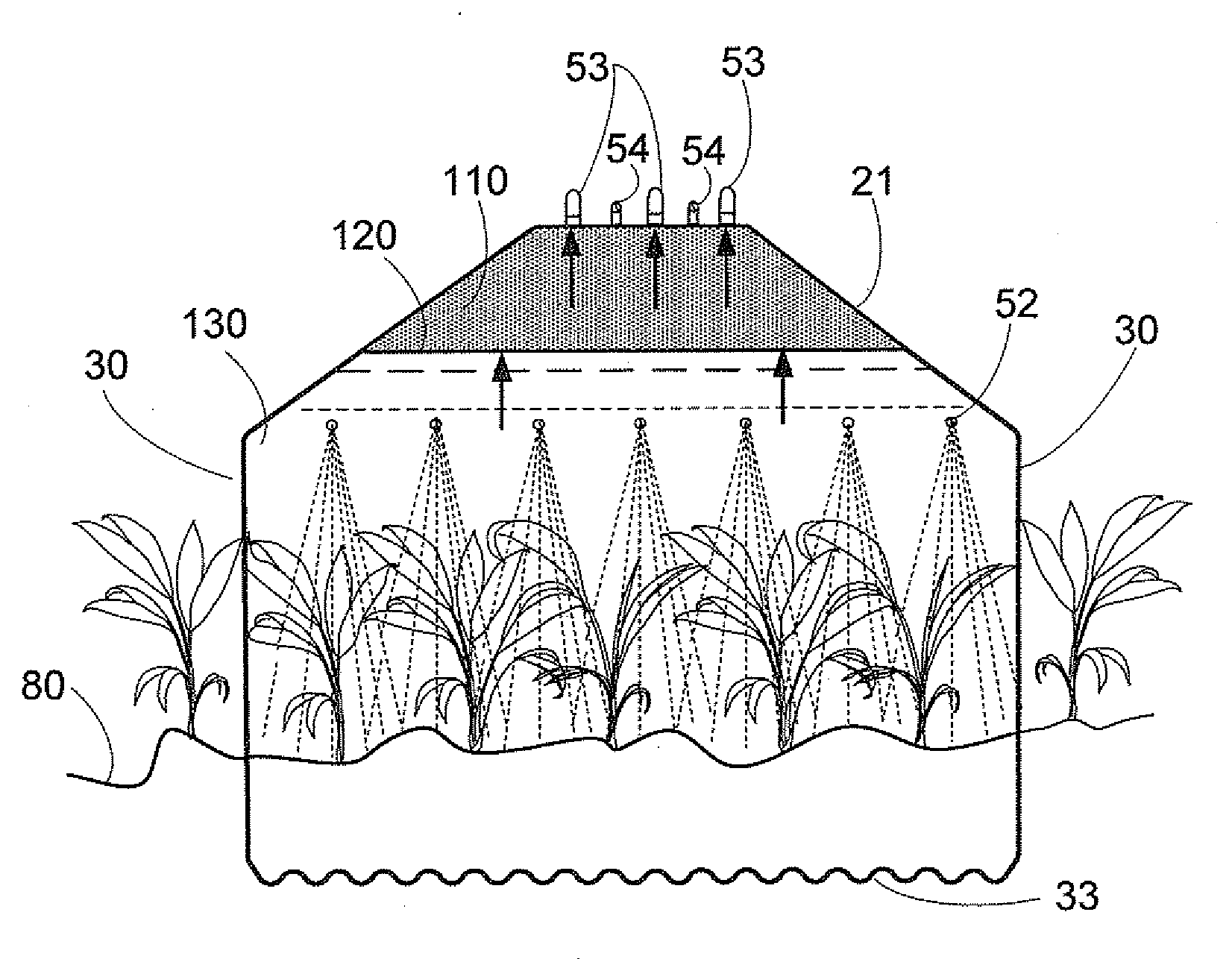
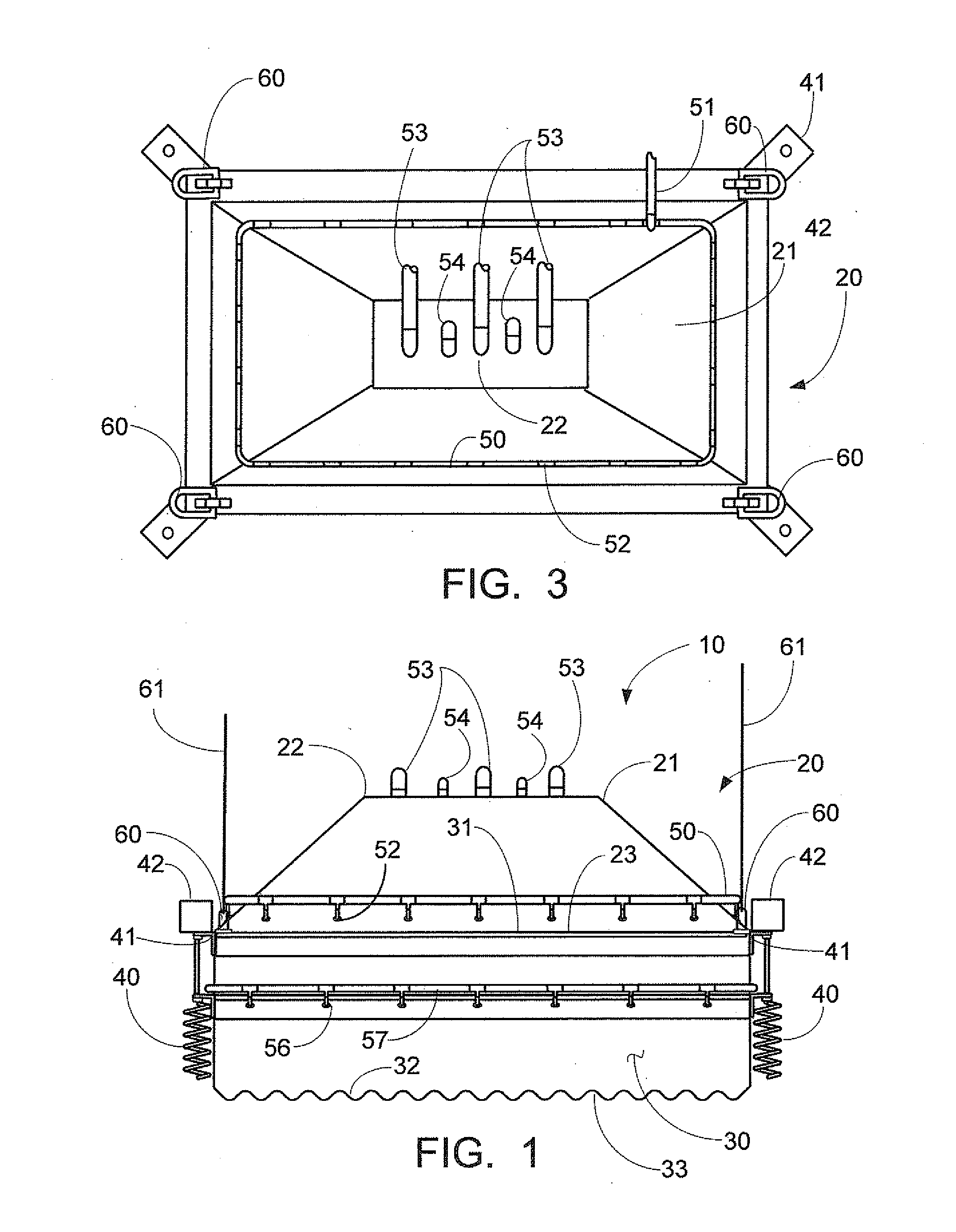
[0017]In FIG. 1 a front elevation of coastal oil recovery system 10 is depicted, showing the containment device 20 with a top hood 21 having an inverted funnel or conical shape and a top surface 22. The lower outer edge 23 of the top hood 21 is connected to the upper edge 31 of the vertical walled sides 30. The bottom edge 32 of the vertical walled sides 30 is shown as a serrated edge 33.

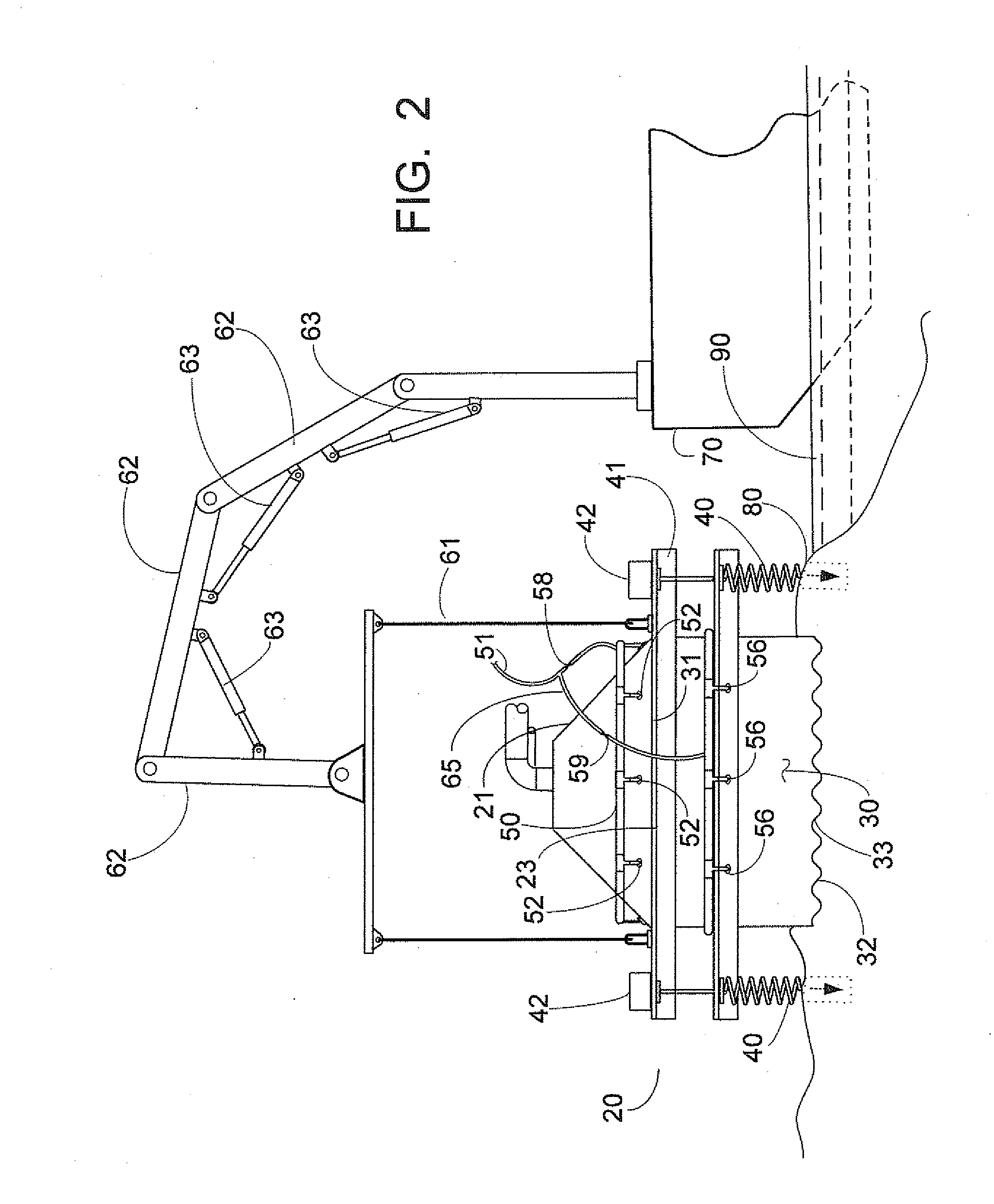
[0018]Also shown in FIG. 1 is a plurality of ground screws 40 supported on struts 41 housing ground screw drivers 42. While not seen in this view, a water supply 51 is feeding either an upper water header 50 or a lower water header 57, in turn respectively feeding either a plurality of upper water jets 52 or a plurality of lower water jets 56 for filling the containment device once firmly embedded in place at the land site to be cleaned.

[0019]At the top surface 22 of the top hood 21 are shown at least one discharge hose 53, vents 54, lifting pads 60 and lifting aim structures 61 for raising and lowe...


PUM


Abstract

A coastal oil recovery system and method for clean up of land based contamination with a containment device having a reverse funnel shaped top hood, rigidly attached to vertical walled sides, a plurality of ground screws to pull the containment device into the soil, a plurality of water jets to fill the containment device and float oil from contaminated soil and vegetation upward into the top hood for extraction by discharge hoses. Due to the shape of the top hood, the depth of the floating oil will increase as it reaches the top of the top hood, facilitating extraction.

Description

[0001]This application claims priority from U.S. Provisional application Ser. No. 61 / 400,191 (“the '191 application”) filed Jul. 23, 2010. The '191 application is incorporated herein by reference.BACKGROUND OF THE INVENTION[0002]This invention relates to systems and methods for fast recovery of oil and waste from “dry land” including beaches, marshland, grasses, ditches and other surfaces including but not limited to coastal lands without physically removing the land.[0003]Numerous devices and methods have been introduced in the past to deal with the environmental devastation caused by the spillage of oil and petroleum substances in waterways, seas and oceans. The need for effective devices and methods has never been more needed than now in light of the terrible oil spill / leak currently threatening the Gulf Coast of the United States. In addition to cleaning up the waterways, seas and oceans, there is also a desperate need to clean up beaches, marshland, grasses, ditches and other c...

Claims


Application Information

Patent Timeline
IPC IPC(8): B09C1/02
CPCB09C1/02
Inventor QUAGLINO, III, ANGELO VINCENT
Owner QUAGLINO III ANGELO VINCENT
Why Eureka
Try Eureka