
Method and apparatus for network port and network address translation

a network port and address translation technology, applied in the field of multi-computer data transfer systems, can solve the problems of limiting the usefulness of existing nat implementations, ipv6 adoption can be costly, and udp does not provide the sequencing or flow control of tcp

Active Publication Date: 2012-01-26
SEMTECH CORP
View PDF13 Cites 31 Cited by
  • Summary
  • Abstract
  • Description
  • Claims
  • Application Information

AI Technical Summary

Problems solved by technology

UDP does not provide the sequencing or flow control of TCP.
Adoption of IPv6 can be costly, has been slow and IPv6 does not provide an imminent solution to the IPv4 address space dilemma.
The time-limited nature of these rules may limit usefulness of existing NAT implementations.
Existing forms of NAT, however, can be complex, cumbersome and error-prone, and extensions typically fail to provide required scalability or even rudimentary security features.
In addition, current port forwarding methods typically have several limitations.
Firstly, address scalability is typically poor because a port forward rule takes away the ability of the NAT to use the port for all IP Source (SRC) addresses.
Secondly, port scalability is also typically poor, because the automatic methods used to set up a port forwarding rule require the terminal to request the incoming port and if that port is already used by another terminal, the request is rejected.
If the NAT was busy, this trial and error approach could be long and inefficient.
Thirdly, routing security is typically poor as the NAT will route all traffic from any server to the terminal thus creating a possible security risk.
Fourthly, malware security is typically poor as automated port forwarding protocols, such as UPnP, aren't secure because any malware or flash entity can setup a port forwarding rule and once compromised, the terminal can compromise all the other devices inside the firewall.
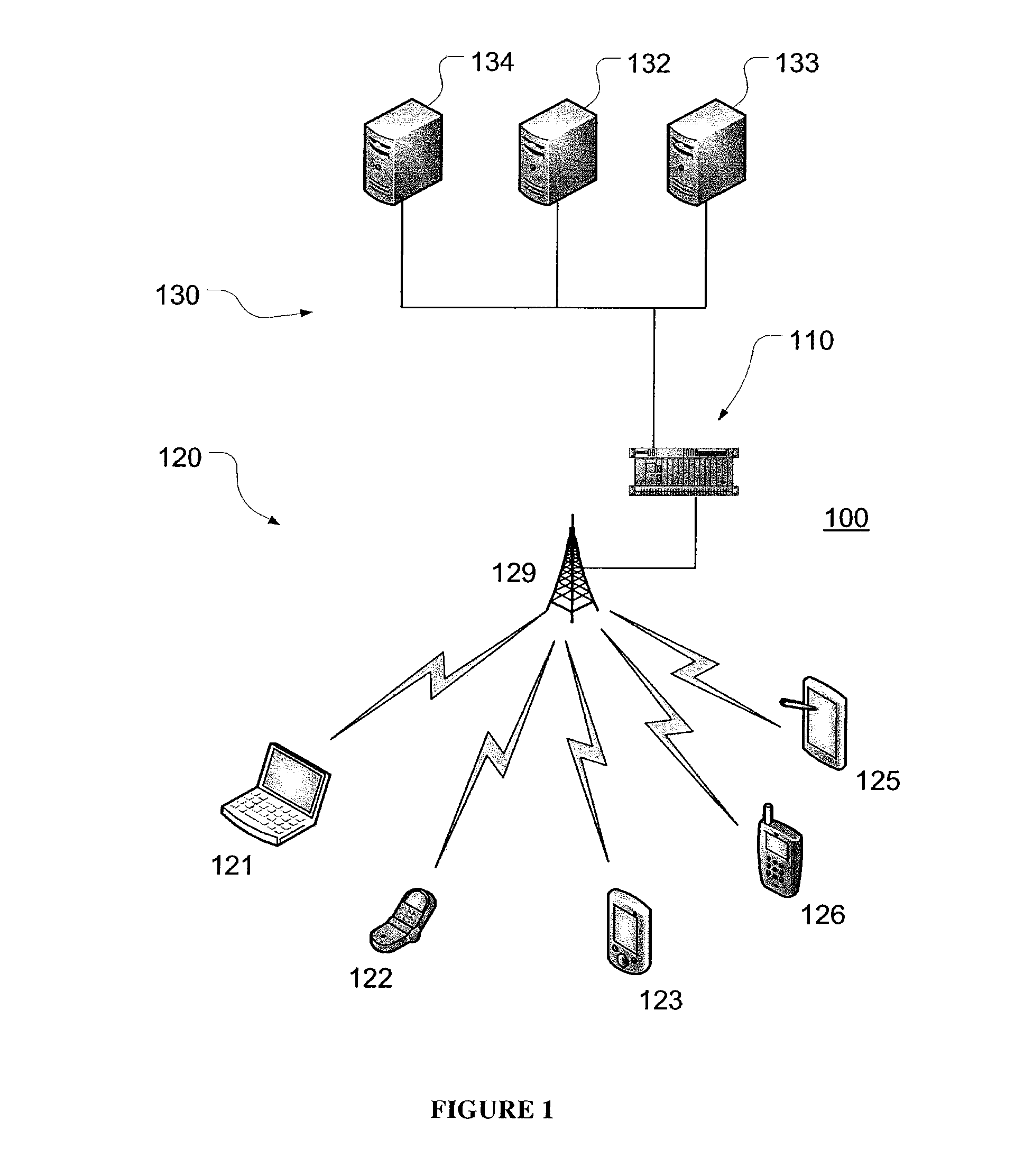
Specific problems with limited addressability may occur when contacting a terminal in a private network from an application server that itself is outside the private network.
Polling of terminals in M2M applications is often dynamic and asynchronous and mobile networks typically do not provide externally routable IP addresses.
Without an externally routable IP address, however, the application server outside an MNO's core network cannot directly contact a terminal within the core network via IP.
A number of solutions to this issue exist but none of them are secure, scalable, or efficient.
Unfortunately, the limited IPv4 address space does not scale to serve the demand for IP addresses of cellular networks.
Furthermore, terminals may send keep-alive messages to prevent routes through NAT from being deactivated, which, however, is not scalable, reliable or efficient as the keep-alive messages may consume significant network resources.
This option is also not scalable because the network would quickly become overloaded with keep-alive messages if many terminals employed this approach.
This option is also not efficient because many M2M terminals send very little data and thus the amount of keep-alive traffic can be higher than the amount of real data sent, and it is not reliable because the length of time a NAT will keep a route open can be dynamic thus periodic transmission of keep-alive messages may not always keep the route open.
In a further solution, a route to a desired terminal in a private network may be established or reactivated by sending a text message from outside to the terminal so that the terminal may seek proper action to activate the route, which however, causes communication delays and requires the terminal to be addressable by a mobile subscriber integrated services digital network number (MSISDN) which in turn requires special configuration and additional interconnections for the server, which is not cost effective given the expense associated with sending text messages.

Method used


Image

  • Method and apparatus for network port and network address translation
  • Method and apparatus for network port and network address translation
  • Method and apparatus for network port and network address translation

Examples


example 1

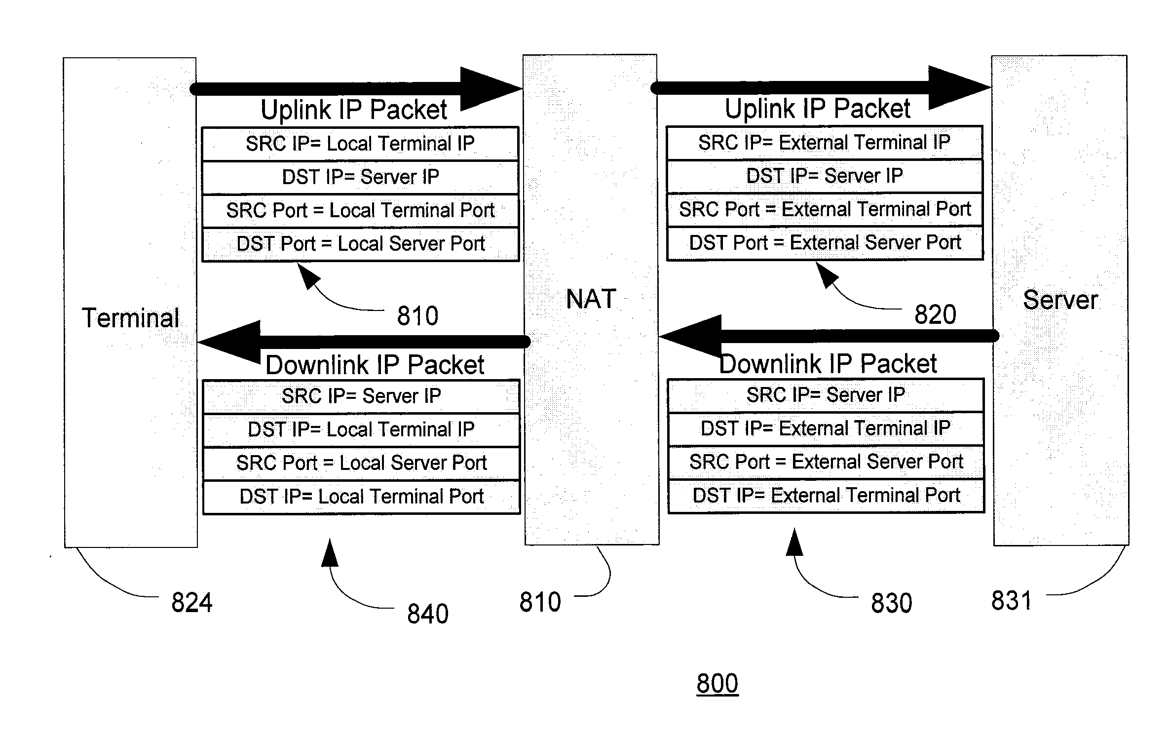
[0097]FIG. 5 illustrates a sequence diagram 500 of an example method according to an embodiment of the present invention for use in a system comprising client 501, NAT device 502, and server 503. The method includes procedure 510 during which the client is activated and attached to and registered with a first network. The client obtains IP address 10.1.2.3, for example via dynamic host control protocol (DHCP) from a DHCP server. The client IP address is part of a private IP address space assigned for communication within the first network between clients including client 501 and NAT device 502. Public IP addresses are being used for communication within the second network between servers including server 503 and NAT device 502. The DHCP server may be integrated with NAT device 502 or a different element.

[0098]Before requesting activation of a DFR, the client 501 determines a FNW server IP address, a FNW client port, and a FNW server port. The client 501 may further determine one or ...

example 2

[0104]FIG. 6 illustrates a sequence diagram 600 of an example method according to another embodiment of the present invention. Example 2 differs from Example 1 generally in that DFR request messages of client 601 additionally include a SNW client port and a SNW server port, which in contrast to Example 1, are now prescribed by client 601 and no longer left to be decided or selected by NAT device 602. This requires different configurations of client 601, NAT device 602 and the communications and procedures 620, 630, and 640. Procedure 610, and communications 650 and 660 are similar to corresponding procedure 510, and communications 550 and 560.

[0105]As illustrated in FIG. 6, the example method can be used in an example system including client 601, NAT device 602, and server 603. The method includes procedure 610 during which the client is activated and attached to and registered with the network. The client obtains private IP address 10.1.2.3, for example via dynamic host control pro...

example 3

[0110]FIG. 7 illustrates a sequence diagram 700 of an example method according to another embodiment of the present invention. Example 3 differs from Example 2 generally in that DFR request messages of client 701 additionally include a SNW client port range and a SNW server port range which in contrast to Example 2 are now again left to be decided by NAT device 702 but within prescribed ranges specified in a DFR request. This embodiment requires different configurations of client 701, NAT device 702 and the communications and procedures 720, 730, and 740. Procedure 710 and communications 750 and 760 are similar to corresponding procedure 610 and communications 650 and 660.

[0111]As illustrated in FIG. 7, the example method can be used in an example system including client 701, NAT device 702, and server 703. The method includes procedure 710 during which the client is activated and attached to and registered with the network. The client obtains private IP address 10.1.2.3, for exampl...


PUM


Abstract

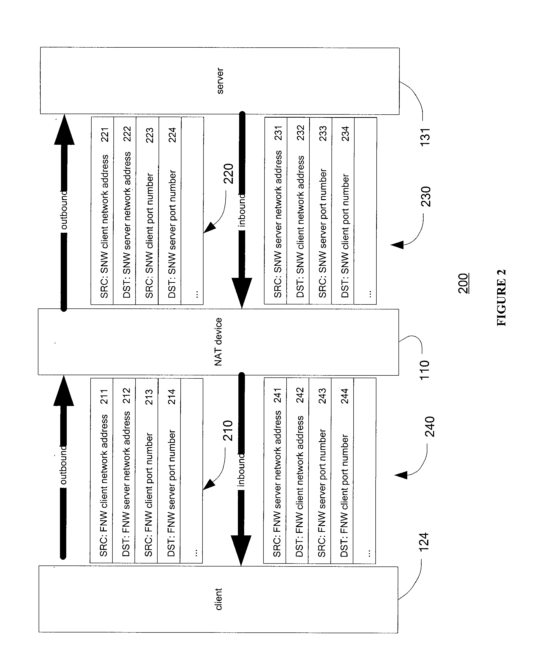
The present invention provides a method and apparatus for network port and network address translation. Several problems with limited addressability may occur when transmitting data packets between a terminal in a first network and a terminal in a second network that is outside the first network. Data forwarding rules are used to define if and how identifiers of data packets to be forwarded between the two networks correlate with each other. According to embodiments, a data forwarding rule includes a first identifier associated with the first network and a second identifier associated with the second network, wherein each identifier has two parts: a source address and source port number corresponding to a source network node, and a destination address and destination port number corresponding to a destination network node.

Description

RELATED APPLICATIONS AND INCORPORATION BY REFERENCE[0001]This application is a continuation-in-part application of international patent application Serial No. PCT / CA2009 / 001622 filed 17 Nov. 2009, which published as PCT Publication No. WO 2010 / 054471 on 20 May 2010, which claims benefit of U.S. provisional patent application Ser. No. 61 / 115,412 filed 17 Nov. 2008.[0002]The foregoing applications, and all documents cited therein or during their prosecution (“appln cited documents”) and all documents cited or referenced in the appln cited documents, and all documents cited or referenced herein (“herein cited documents”), and all documents cited or referenced in herein cited documents, together with any manufacturer's instructions, descriptions, product specifications, and product sheets for any products mentioned herein or in any document incorporated by reference herein, are hereby incorporated herein by reference, and may be employed in the practice of the invention. More specifical...

Claims


Application Information

Patent Timeline
Patent Type & Authority Applications(United States)
IPC IPC(8): G06F15/16
CPCH04L29/12377H04L61/2582H04L61/2517H04L29/12547H04L12/46H04L12/56
Inventor VOS, GUSTAV GERALDKAVANAUGH, RICHARD THOMASMITCHELL, ANDREW HASLEY WATSONWAUNG, WILLIAM YIH YUAN
Owner SEMTECH CORP
Learn More