Microfluidic separation system

a technology of microfluidics and separation systems, applied in the field of microfluidics, can solve the problems of reducing the number of effective binding sites to targets, unable to form stable colloidal suspensions, and low surface-to-volume ratio of larger magnetic particles compared to smaller ones

Inactive Publication Date: 2012-02-02
AGENCY FOR SCI TECH & RES
View PDF0 Cites 11 Cited by
  • Summary
  • Abstract
  • Description
  • Claims
  • Application Information

AI Technical Summary

Problems solved by technology

However, they do not form stable colloidal suspensions easily.
Additionally, the surface-to-volume ratio is low for larger magnetic particles compared to smaller ones.
This tends to reduce the number of effective binding sites to targets, especially when the targets are present in low density.
These various factors lead to low separation efficiency for larger magnetic particles.
This metho

Method used


Image

  • Microfluidic separation system
  • Microfluidic separation system
  • Microfluidic separation system

Examples


Embodiment Construction

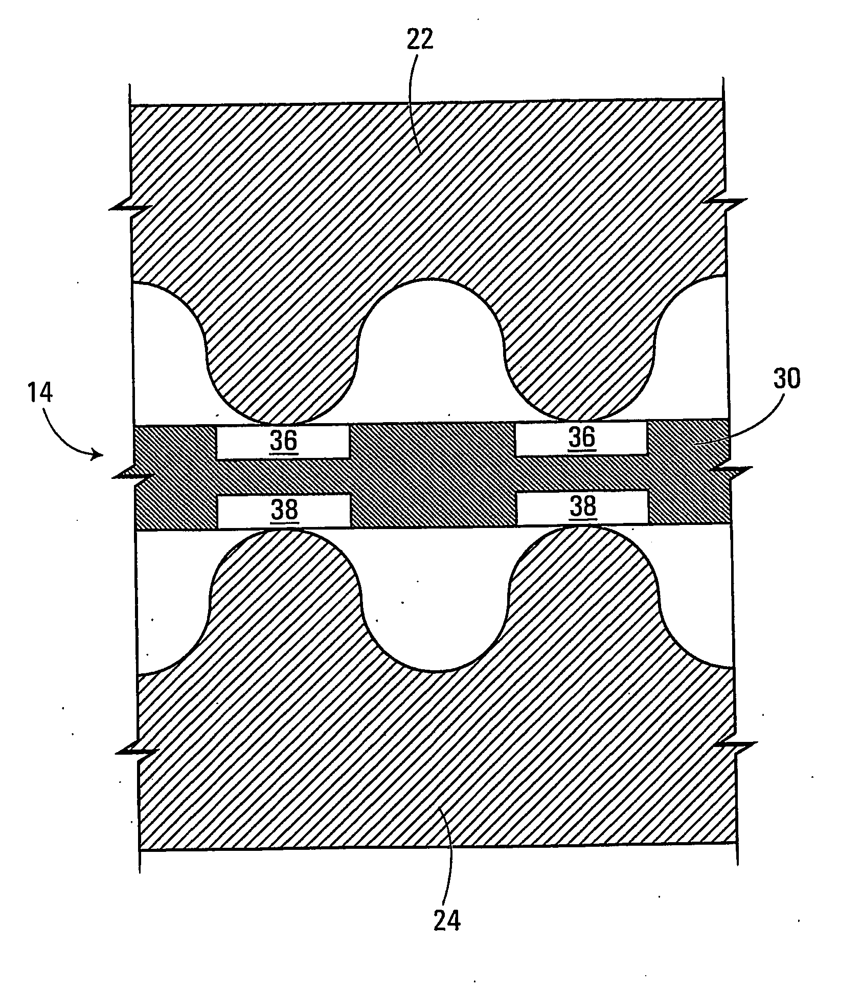
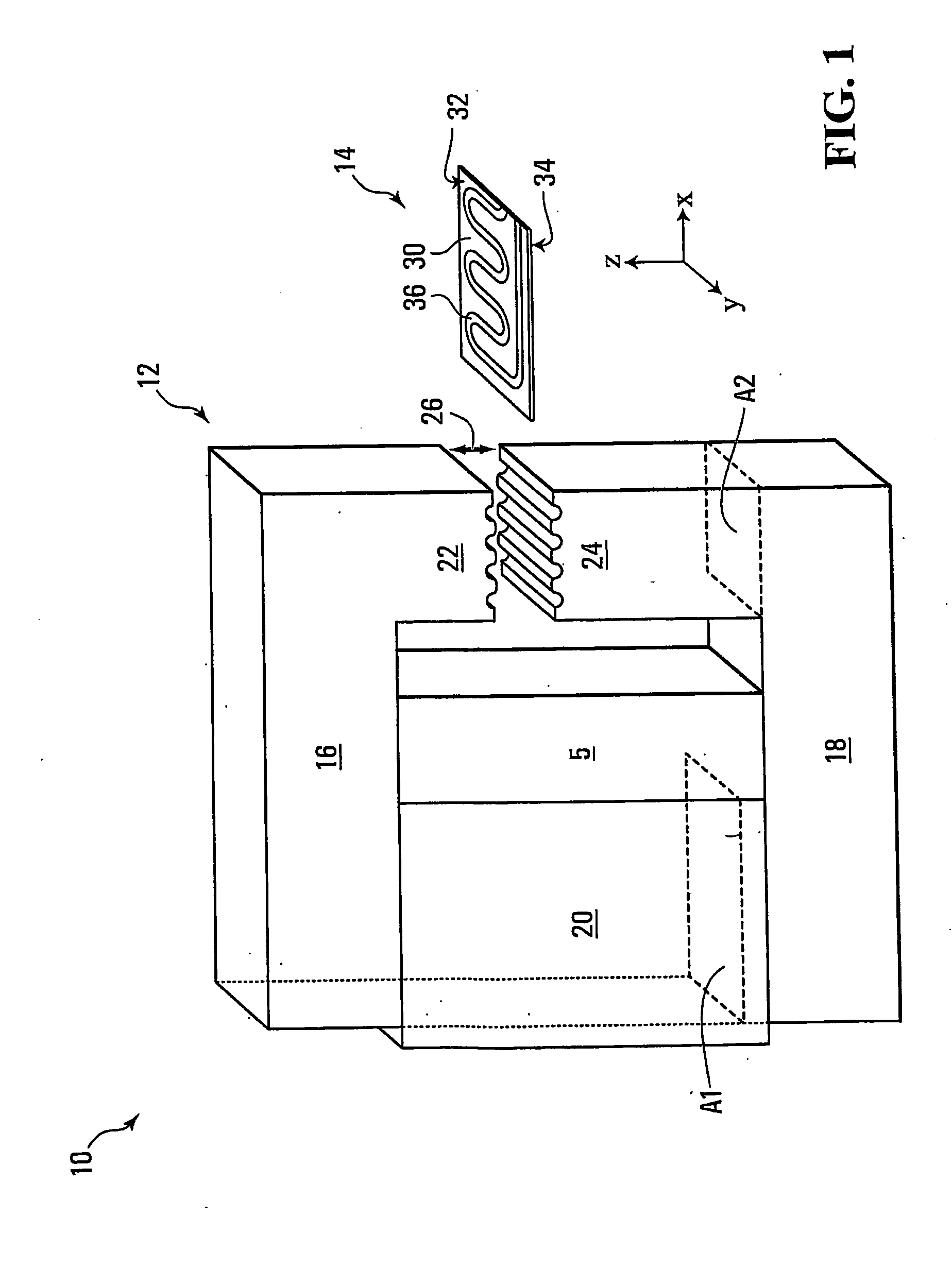
[0044]With reference to FIG. 1, there is shown a microfluidic separation system 10, which includes a magnetic separator 12 and a microfluidic chip 14. The magnetic separator 12 includes a first magnetically conductive member 16 and a second magnetically conductive member 18. Also provided is a magnetic energy source 20 that is connected to the first and second members 16, 18. In some non-limiting embodiments, the magnetic energy source 20 may be a permanent magnet or an arrangement (e.g., a stack) of permanent magnets. Non-limiting examples of suitable permanent magnets are those made from a rare earth material, such as Nd—Fe—B. In other non-limiting embodiments, the magnetic energy source 20 may be an electromagnet subjected to direct current (DC) or alternating current (AC). The strength of the magnetic energy source 20 is not particularly limited. For example, a suitable minimum value for the maximum magnetic energy is 40 MGOe (mega giga oersteds), although other values for the m...


PUM

PropertyMeasurementUnit
Flow rateaaaaaaaaaa
Magnetic fieldaaaaaaaaaa
Volumeaaaaaaaaaa

Abstract

A microfluidic separation system, which comprises a magnetic separator, which itself comprises a magnetic energy source; first and second magnetically conductive members leading from the magnetic energy source and having respective terminal ends that are separated by a gap over which a magnetic field is applied due to the magnetic energy source. The separation system further comprises a microfluidic chip for insertion into the gap, which comprises a body defining channels on respective faces of the body; and an exterior lining that seals the plurality of channels to allow separate test sample volumes to circulate in at least two of the channels. Upon insertion of the chip into the gap, a first test sample volume is confined to circulating closer to the terminal end of the first member and a second test sample volume is confined to circulating closer to the terminal end of the second member.

Description

CROSS-REFERENCE TO RELATED APPLICATION[0001]The present application claims the benefit under 35 U.S.C. 119(e) of U.S. Provisional Patent Application Ser. No. 60 / 935,443 to Ying et al., filed Aug. 13, 2007, hereby incorporated by reference herein.FIELD OF THE INVENTION[0002]The present invention relates generally to microfluidics and, more particularly, to a microfluidic separation system that comprises a magnetic separator and a microfluidic chip.BACKGROUND[0003]Microfluidic devices can be used to conduct biomedical research and create clinically useful technology. Particular types of microfluidic devices rely on the use of a magnetic field to separate small volumes of magnetic particles from a larger test sample that is mostly non-magnetic. In the separation process, tiny magnetic particles coated with targeting monomers or polymers (e.g., proteins) are used to specifically bind with targeted material such as cells, nucleic acids and proteins. This allows a wide range of targeted m...

Claims


Application Information

Patent Timeline
IPC IPC(8): B03C1/035B81B1/00
CPCB03C1/002B03C1/0335B03C1/035B03C1/32B03C2201/18G01N35/0098B03C1/0332B03C1/288B03C2201/22B03C2201/26B03C1/01
Inventor YING, JACKIE Y.XU, GUOLINLEE, YOKE SAN DANIEL
Owner AGENCY FOR SCI TECH & RES
Why Eureka
Try Eureka