Venting gas from a tank

a technology of gas venting and fuel tanks, which is applied in water supply installations, containers, packaged goods types, etc., can solve the problems of large positive pressure difference between the tank and the atmosphere, undue strain, and difficulty in putting further fuel in the tank

Active Publication Date: 2012-02-02
AIRBUS OPERATIONS LTD
View PDF12 Cites 13 Cited by
  • Summary
  • Abstract
  • Description
  • Claims
  • Application Information

AI Technical Summary

Benefits of technology

[0010]The present invention provides, according to a first aspect, a tank vent device for venting gas from a tank, the device comprising a gas inlet for receiving gas from a vent outlet of the tank, a gas outlet for discharging the gas received from the vent outlet of the tank, and a pressure valve connecting the gas inlet and gas outlet, wherein the pressure valve is connected to a control pressure input and is controllable by control pressure supplied at the control pressure input, whereby, in use, the pressure valve is controlled by the control pressure to open and close so as to regulate the flow of gas between the gas inlet and the gas outlet.

Problems solved by technology

If there is inadequate venting, the pressure build up in the tank is significant and can make it very difficult to put further fuel in the tank.
Secondly, a pressure build up can result in a large positive pressure differential between the tank and the atmosphere.
Any pressure differential puts undue strain on the tanks and can cause damage to them and their surrounding structure.
However, use of the vapour fuel recovery system of GB 2 321 639 A results in a vapour flow restriction (even when the bypass flow element is open).
Therefore, the system causes pressure to build up in the fuel tank during refuel and therefore slows down the refuelling rate that can be achieved and puts undue strain on the tank.
The system is also not suitable for use with jet fuel or for use on an aircraft.
However, the system disclosed contains no safety features that could prevent over or under pressure of the fuel tank or prevent the possibility of flame propagation via the fuel hose into the fuel tank.
The system, however, does contain an alarm which can be used to show fuel flow problems or hose kinking.
Failure of the safety system by an electrical short would give rise to a risk of fuel vapour ignition.
Furthermore, the system disclosed contains no safety features that could prevent the possibility of flame propagation via the discharge line into the aircraft tank.

Method used


Image

  • Venting gas from a tank
  • Venting gas from a tank
  • Venting gas from a tank

Examples


Embodiment Construction

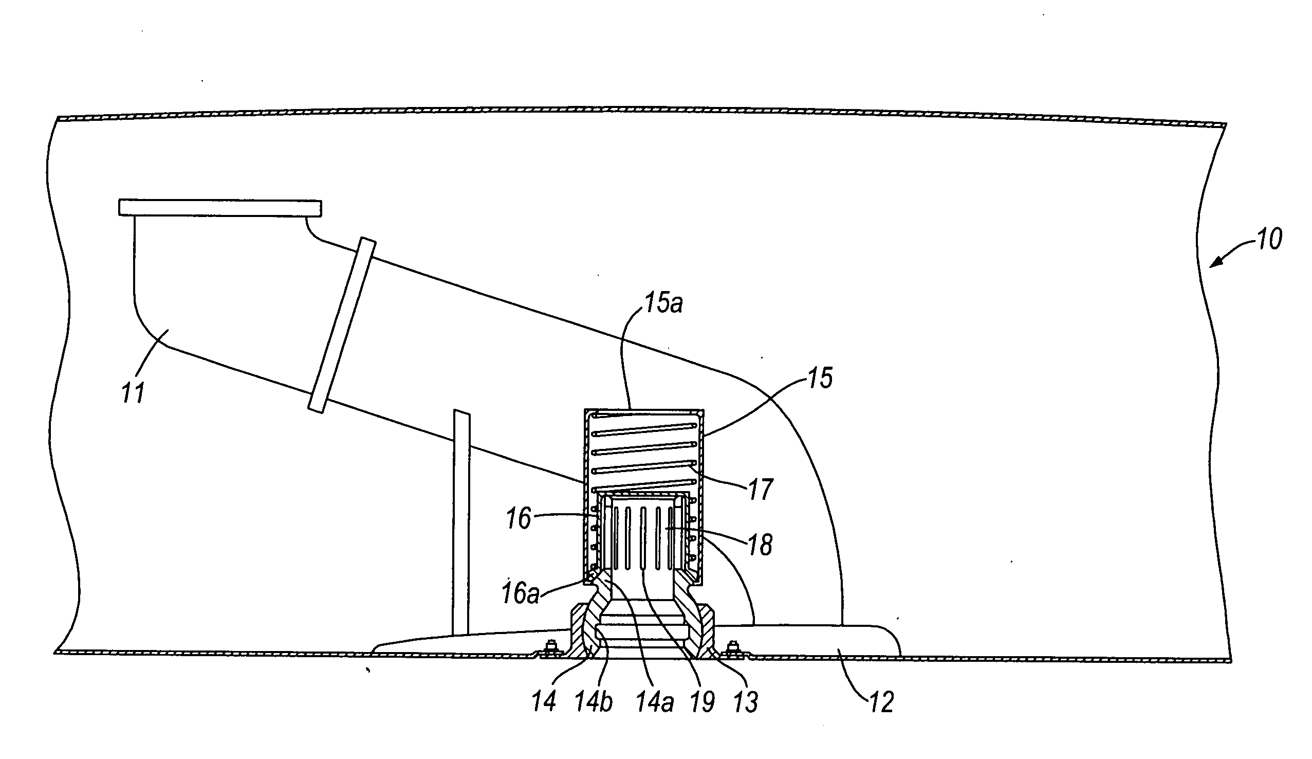
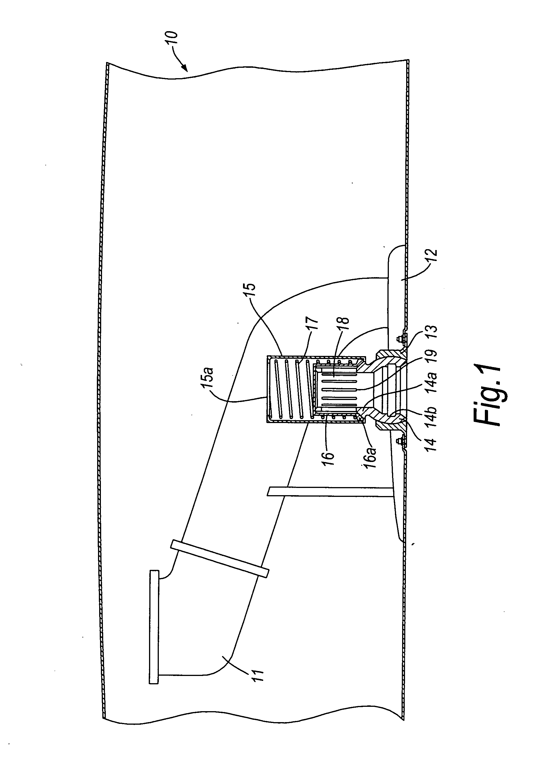
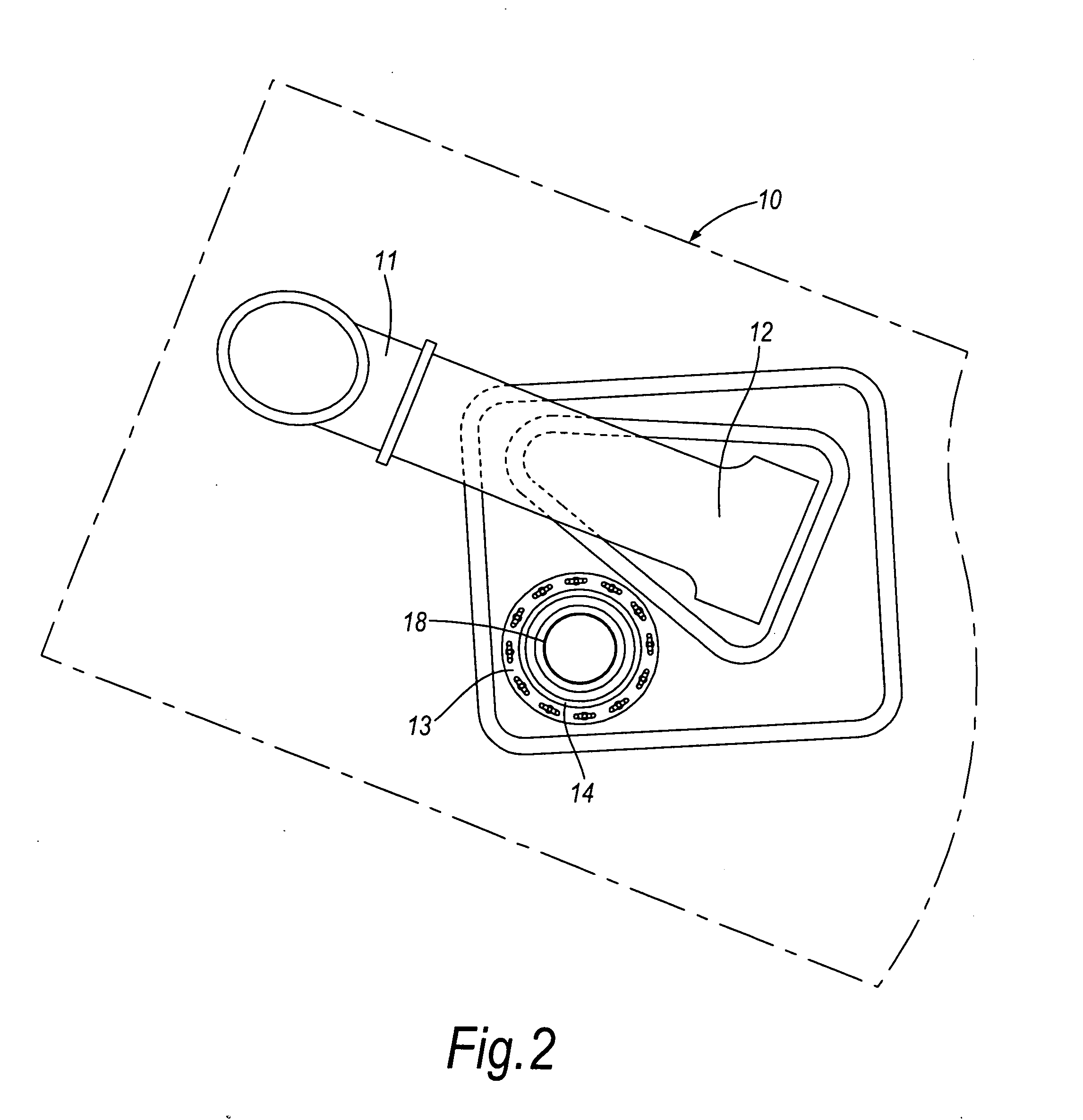
[0061]FIGS. 1 and 2 show partial views of a vent tank 10 in the outboard wing of an aircraft. The vent tank 10 conventionally includes a flame arrestor 11 and a NACA (National Advisory Committee for Aeronautics) duct 12. The vent tank 10 also includes a valve assembly situated within the NACA duct 12. The valve assembly includes a socket 13 which is bolted into place within the NACA duct.

[0062]A ball portion 14 of the valve assembly is contained within the socket 13 to provide a rotatable gimble joint of the valve assembly to the vent tank 10. The ball portion 14 has a bore including an internal circular groove 14b. At the top of the ball portion is a slanted valve seat 14a. A valve casing 15 is mounted above the ball portion 14 and includes an upper opening 15a to the inside of the vent tank 10.

[0063]Within the valve casing 15 is a moveable cap 16. The cap 16 includes a slanted valve seat 16a at the bottom. This valve seat 16a corresponds to the slanted valve seat 14a of the ball p...


PUM

PropertyMeasurementUnit
pressureaaaaaaaaaa
atmospheric pressureaaaaaaaaaa
pressureaaaaaaaaaa

Abstract

The present invention provides a tank vent device for venting gas from a tank 10 comprising a gas inlet 107 for receiving gas from a vent outlet of the tank, a gas outlet 109 for discharging the gas received, and a pressure valve 70 connecting the gas inlet and gas outlet, wherein the pressure valve is connected to a control pressure input 108 and is controllable by control pressure supplied at the control pressure input, whereby, in use, the pressure valve is controlled by the control pressure to open and close so as to regulate the flow of gas between the gas inlet and the gas outlet. The present invention also provides a vent tank 10, methods of venting gas from a tank including a method including the steps of connecting a tank vent device to a tank and supplying gas at a lower pressure than the pressure of the tank to the tank vent device and a method of refuelling an aircraft.

Description

BACKGROUND OF THE INVENTION[0001]The present invention concerns the venting of gas from fuel tanks. In particular, it concerns venting fuel tanks of aircraft. Also particularly, but not exclusively, this invention concerns a tank vent device for venting gas from a tank. The invention also concerns a vent tank, a method of venting gas from a tank and a method of refuelling an aircraft including performing the method of venting gas.[0002]It is important to vent a tank for two reasons. Firstly, a tank must be vented to enable the tank to be efficiently filled with fuel. If there is inadequate venting, the pressure build up in the tank is significant and can make it very difficult to put further fuel in the tank. Secondly, a pressure build up can result in a large positive pressure differential between the tank and the atmosphere. A negative pressure differential could also arise (depending on the atmospheric pressure). Any pressure differential puts undue strain on the tanks and can ca...

Claims


Application Information

Patent Timeline
Patent Type & Authority Applications(United States)
IPC IPC(8): B64D37/02B64D37/06B65B3/04B65D90/34F15D1/00
CPCB64F1/28B64D37/005Y10T137/0318
Inventor FRENCH, CLIVE
Owner AIRBUS OPERATIONS LTD
Why Eureka
Try Eureka