Deflection roller, deflection roller package and wire saw

Pending Publication Date: 2022-11-10
HILTI AG
View PDF0 Cites 0 Cited by
  • Summary
  • Abstract
  • Description
  • Claims
  • Application Information

AI Technical Summary

Problems solved by technology

The individual deflection rollers have to adapt their rotational speed independently of one another to the running speed of the saw wire, otherwise they would be cut in a very short time.
Dust and water clog the rotary bearings.
The high rotational speed induces wear in the sealing element.

Method used


Image

  • Deflection roller, deflection roller package and wire saw
  • Deflection roller, deflection roller package and wire saw
  • Deflection roller, deflection roller package and wire saw

Examples


Embodiment Construction

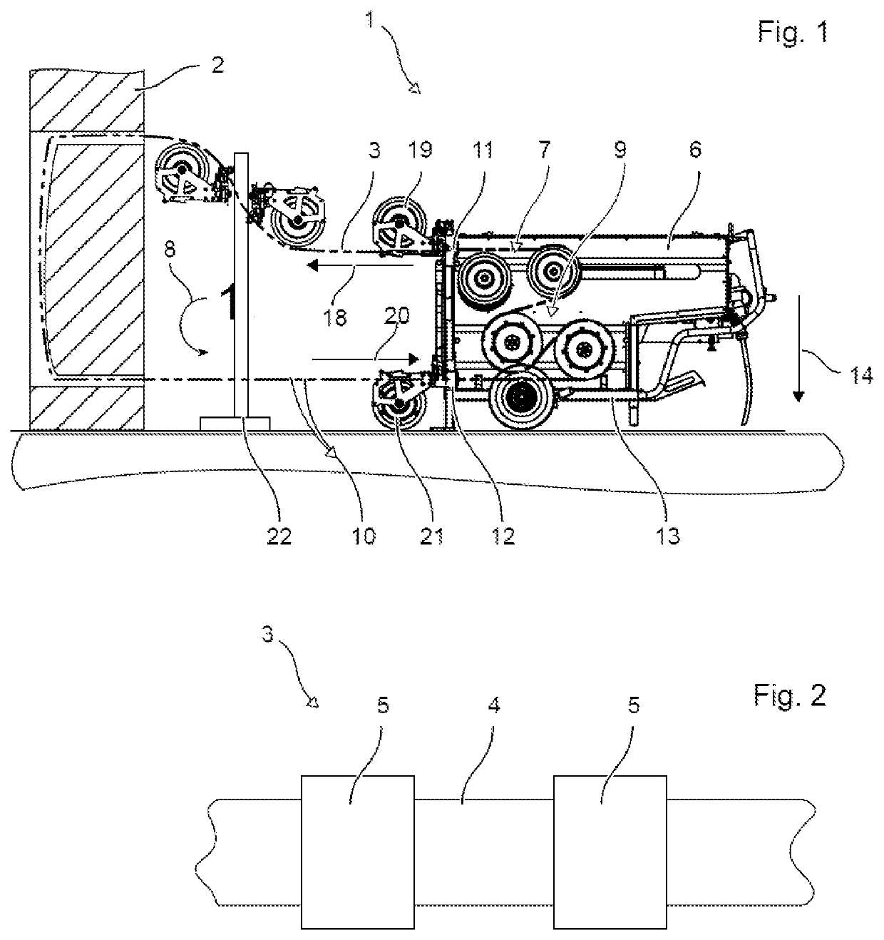
[0037]FIG. 1 shows an exemplary construction of a wire saw 1 in a side view. The wire saw 1 is suitable for example for cutting walls, blocks, pillars, buildings and other large structures or structural elements 2 consisting of natural stone, concrete, bricks, or other mineral building materials. The building materials can also contain a reinforcement made of steel. The wire saw 1 allows different cutting patterns; for example, cutting surfaces can be planar, cylindrical, conical or prismatic.

[0038]The wire saw 1 cuts the workpieces 2 by means of an endless saw wire 3 in the form of a loop. The saw wire 3 has a carrier wire 4 whose ends are connected to one another to form a loop. The carrier wire 4 is flexible. The carrier wire 4 can be based for example on a wire cable. Arranged along the carrier wire 4 on its circumference are a plurality of cutting bodies 5 for mineral building materials. The cutting bodies 5 are for example made of sintered hard metal and / or provided with diamo...


PUM

PropertyMeasurementUnit
circumferenceaaaaaaaaaa
outer radiusaaaaaaaaaa
inner radiusaaaaaaaaaa

Abstract

A deflection roller (32) for a deflection roller package (33) of a wire saw (1), having a wheel (32), a pivot bearing (42) and a sealing element (55). The wheel (32) has a raceway (45) along the periphery thereof for guiding a saw wire (3) of the wire saw (1). The pivot bearing (42) is coaxially inserted in the wheel (32). An outer sleeve (51) protrudes from a lateral surface (49) of the wheel (32). An inner sleeve (50) protrudes from a lateral surface opposite the one lateral surface (49). A radius (53) of the inner sleeve (50) is smaller than a radius (52) of the outer sleeve (51). The sealing element (55) is placed on the outer sleeve (51) or inserted into the inner sleeve (50).

Description

FIELD OF THE INVENTION[0001]The present invention relates to a deflection roller, to a deflection roller package and to a wire saw.SUMMARY OF THE INVENTION[0002]A deflection roller according to the invention for a deflection roller package of a wire saw has a wheel, a rotary bearing and a sealing element. The wheel has along its circumference a running groove for guiding a saw wire of the wire saw. The rotary bearing is inserted coaxially into the wheel. An outer sleeve projects from one lateral surface of the wheel. An inner sleeve projects from a lateral surface opposite to the one lateral surface. A radius of the inner sleeve is smaller than a radius of the outer sleeve. The sealing element is placed on the outer sleeve or inserted into the inner sleeve.[0003]The deflection rollers are exposed to high loading. The individual deflection rollers have to adapt their rotational speed independently of one another to the running speed of the saw wire, otherwise they would be cut in a v...

Claims


Application Information

Patent Timeline
Patent Type & Authority Applications(United States)
IPC IPC(8): B23D57/00B65H57/16B65H57/14
CPCB23D57/0053B65H57/16B65H57/14B65H2701/354B65H2402/52B66D3/06
Inventor RIEGER, HANS-JOERGPLATTNER, DAVID
Owner HILTI AG
Why Eureka
Try Eureka