Power Supply For A Load Control Device

Active Publication Date: 2012-02-02
LUTRON TECH CO LLC
View PDF2 Cites 37 Cited by
  • Summary
  • Abstract
  • Description
  • Claims
  • Application Information

AI Technical Summary

Benefits of technology

[0008]According to an embodiment of the present invention, a load control device adapted to be coupled between an AC power source and an electrical load for controlling the power delivered to the load comprises a power supply having an energy storage capacitor and a charge pump circuit adapted to conduct an input charging current through the load and to conduct an output charging current through the energy storage capacitor to thus generate a DC supply voltage across the energy storage capacitor, where the output charging current has a magnitude greater than the inp

Problems solved by technology

As a result, not all of the AC line voltage of the AC power source is available to power the electrical load and the electrical load may not operate properly when the two-wire electronic switch is controlling the load to be on.
In addition, the power supply must draw current through the controlled electrical load in order to charge, which may cause problems for some types of electrical loads.
For example, when the electrical load

Method used


Image

  • Power Supply For A Load Control Device
  • Power Supply For A Load Control Device
  • Power Supply For A Load Control Device

Examples


Embodiment Construction

[0025]The foregoing summary, as well as the following detailed description of the preferred embodiments, is better understood when read in conjunction with the appended drawings. For the purposes of illustrating the invention, there is shown in the drawings an embodiment that is presently preferred, in which like numerals represent similar parts throughout the several views of the drawings, it being understood, however, that the invention is not limited to the specific methods and instrumentalities disclosed.

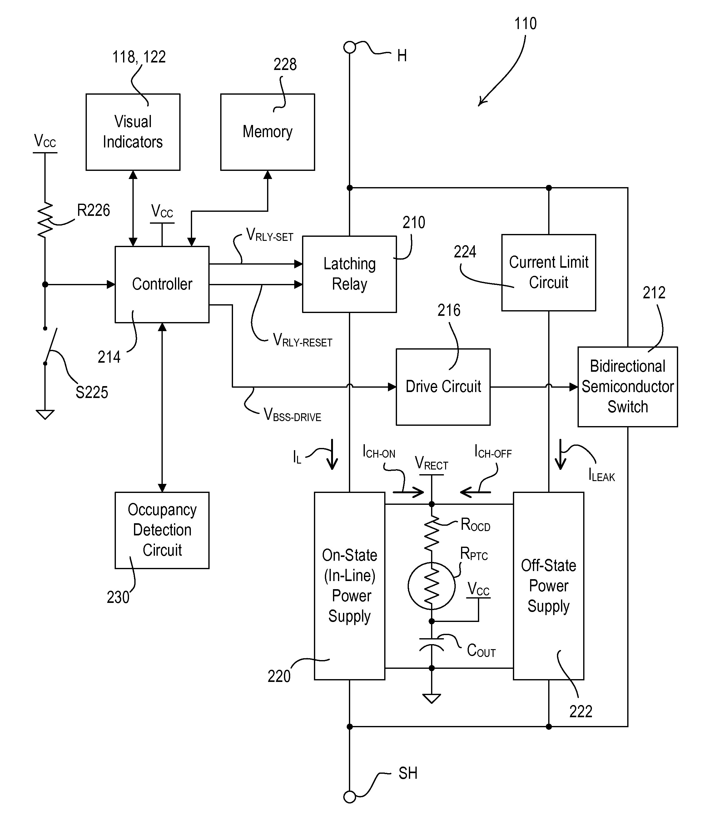
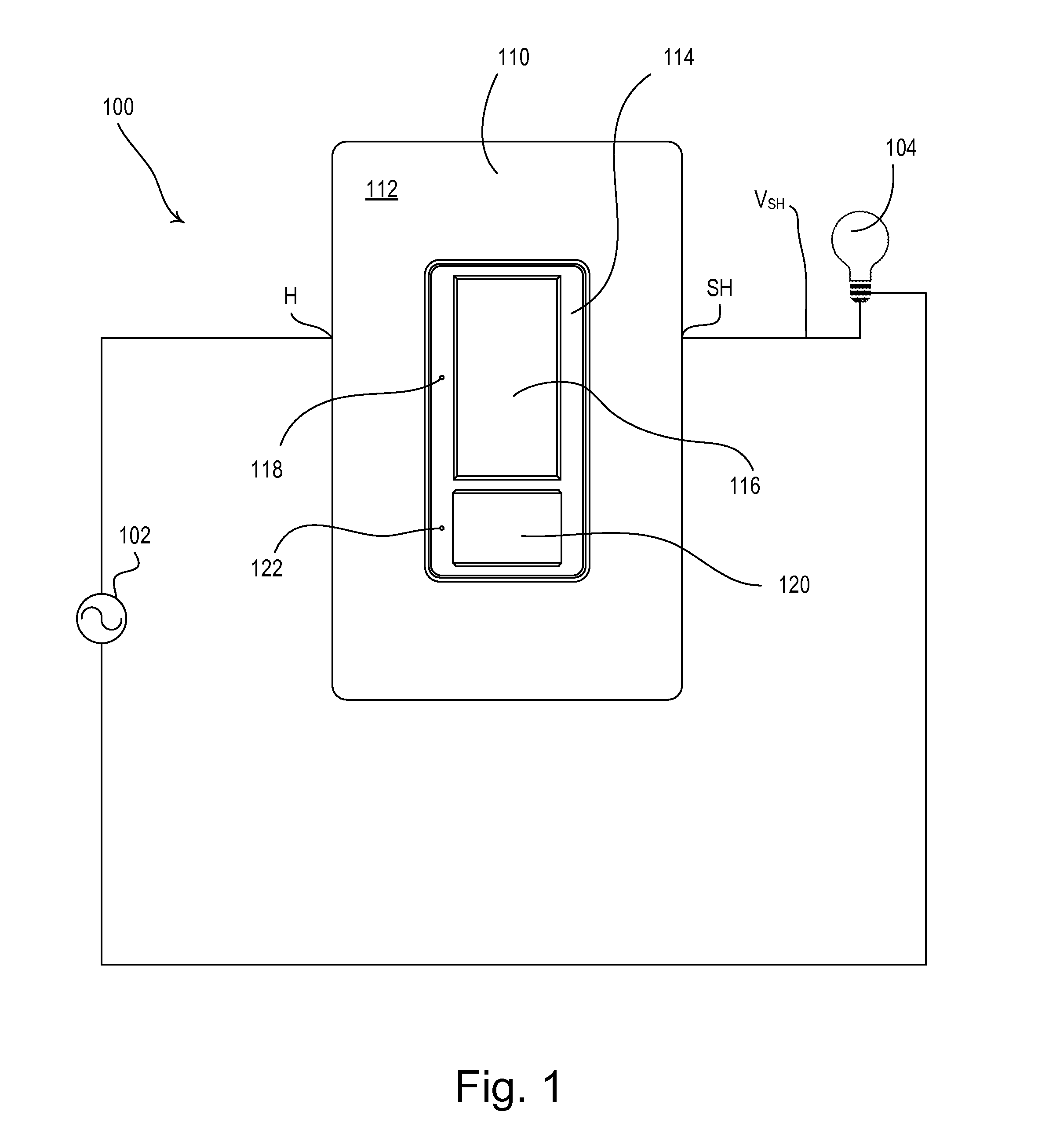
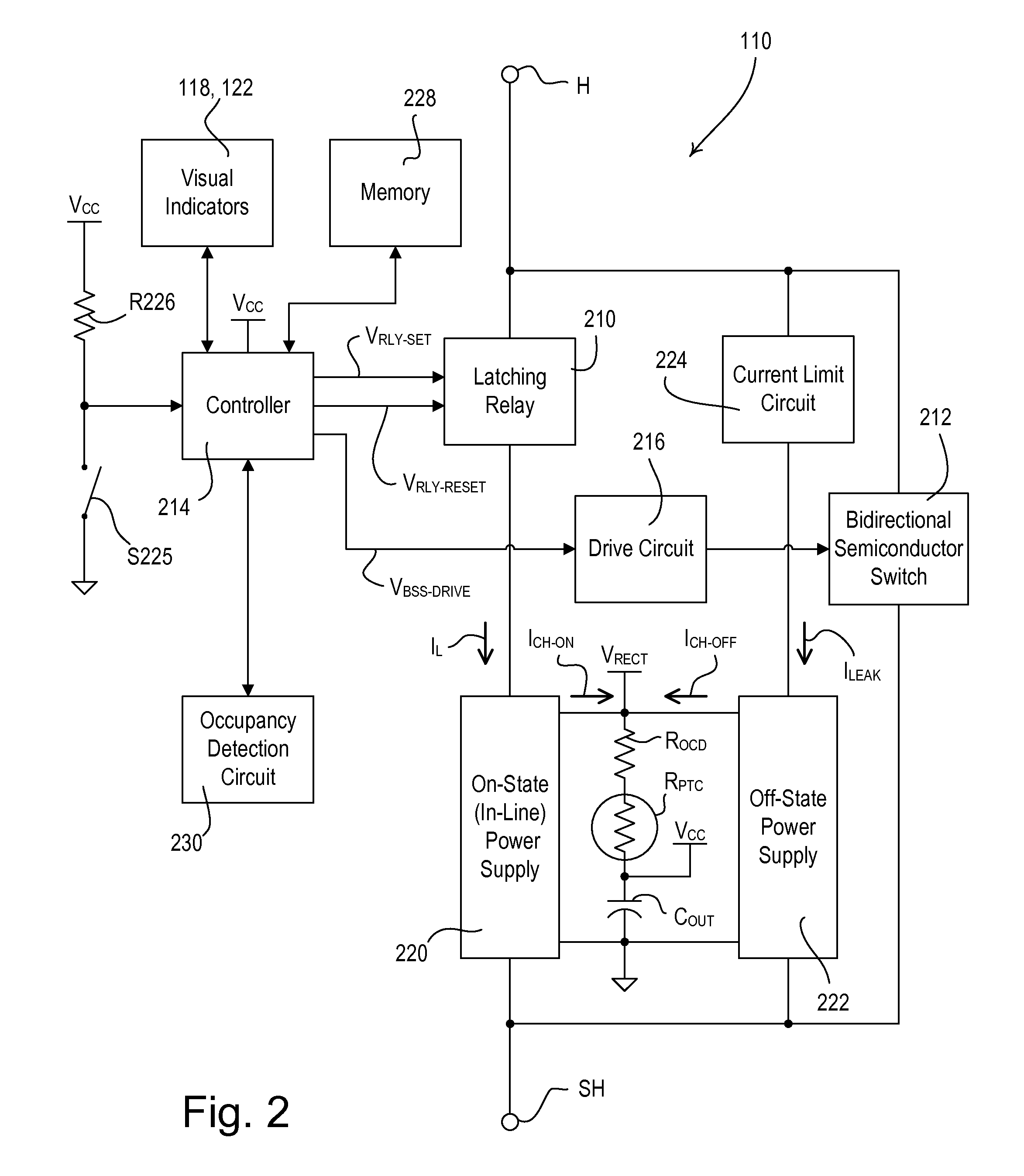
[0026]FIG. 1 is a simple block diagram of a lighting control system 100 including a two-wire electronic switch 110 according to an embodiment of the present invention. The electronic switch 110 comprises a hot terminal H and a switched hot terminal SH and is adapted to be coupled in series electrical connection between an alternating current (AC) power source 102 (e.g., 120 VAC @ 60 Hz or 240 VAC @ 50 Hz) and a lighting load 104 for controlling the power delivered to the lightin...


PUM

PropertyMeasurementUnit
Poweraaaaaaaaaa
Currentaaaaaaaaaa
Electrical conductoraaaaaaaaaa

Abstract

A load control device adapted to be coupled between an AC power source and an electrical load for controlling the power delivered to the load includes a power supply having an energy storage capacitor and a charge pump circuit adapted to conduct an input charging current through the load and to conduct an output charging current through the energy storage capacitor to thus generate a DC supply voltage across the energy storage capacitor, where the output charging current has a magnitude greater than the input charging current. The charge pump circuit includes a switched capacitor operable to charge through the load during a first half-cycle, and to discharge into the energy storage capacitor in a second, subsequent half-cycle. The charge pump circuit operates at line frequency and the magnitude of the input charging current is substantially small so as to avoid generating noise in a noise-sensitive circuit of the load control device.

Description

BACKGROUND OF THE INVENTION[0001]1. Field of the Invention[0002]The present invention relates to load control devices for control of the power delivered from an alternating-current (AC) power source to an electrical load, and more particularly, to a two-wire electronic switch having a power supply that draws only a small amount of current through the load when the load is off[0003]2. Description of the Related Art[0004]Typical load control devices are operable to control the amount of power delivered to an electrical load, such as a lighting load or a motor load, from an alternating-current (AC) power source. Wall-mounted load control devices are adapted to be mounted to standard electrical wallboxes. A dimmer switch comprises a controllably conductive device (e.g., a bidirectional semiconductor switch, such as, a triac), which is coupled in series between the power source and the load. The controllably conductive device is controlled to be conductive and non-conductive for portions...

Claims


Application Information

Patent Timeline
IPC IPC(8): H02M5/257
CPCH02M1/08H02M3/07H05B37/0227H02M2001/0006H05B33/0815H02M5/293H05B47/115H02M1/0006Y02B20/40
Inventor CARMEN, DANIEL F.
Owner LUTRON TECH CO LLC
Why Eureka
Try Eureka