Single RF receiver chain architecture for gps, galileo and glonass navigation systems, and other circuits, systems and processes

a single-chip and receiver chain technology, applied in the direction of digital transmission, amplitude demodulation, instruments, etc., can solve the problems of reducing the attractiveness of a product to potential customers, increasing the cost of chips and systems, and preventing adoption of such technology

Active Publication Date: 2012-02-02
TEXAS INSTR INC
View PDF0 Cites 74 Cited by
  • Summary
  • Abstract
  • Description
  • Claims
  • Application Information

AI Technical Summary

Benefits of technology

[0017]Generally, a further form of the invention involves an electronic circuit for separating frequency-overlapped GLONASS and GPS overlapped in an approximately 20 MHz passband, and the circuit includes a multiple-path analog-to-digital converter circuit (ADC), a sampling rate circuit coupled to concurrently operate the analog-to-digital converter circuit at a sampling rate between about 60 Msps and about 80 Msps, and a digital processing circuit including storage defining complex de-rotation and low pass filtering, the digital processing circuit fed by the analog-to-digital converter circuit and operable A) to establish an access rate and respective distinct phase increments for the complex de-rotation, and B) to execute the complex de-rotation by combinations of trigonometric multiplications using the distinct phase increments approximately concurrently and C) to execute the low pass filtering on the complex de-rotation resulting at the access rate and respective distinct phase increments, whereby to deliver GPS and Glonass signals separated from each other.

Problems solved by technology

Dual RF chains are likely to be double in terms of area and power, which is problematic and may diminish the attractiveness of a product to potential customers.
Using technology as above, even if a low-noise amplifier (LNA) were shared, increases chip and system cost to include or enable Glonass, for instance, in a GPS navigation product, which impedes adoption of such technology.

Method used


Image

  • Single RF receiver chain architecture for gps, galileo and glonass navigation systems, and other circuits, systems and processes
  • Single RF receiver chain architecture for gps, galileo and glonass navigation systems, and other circuits, systems and processes
  • Single RF receiver chain architecture for gps, galileo and glonass navigation systems, and other circuits, systems and processes

Examples


Embodiment Construction

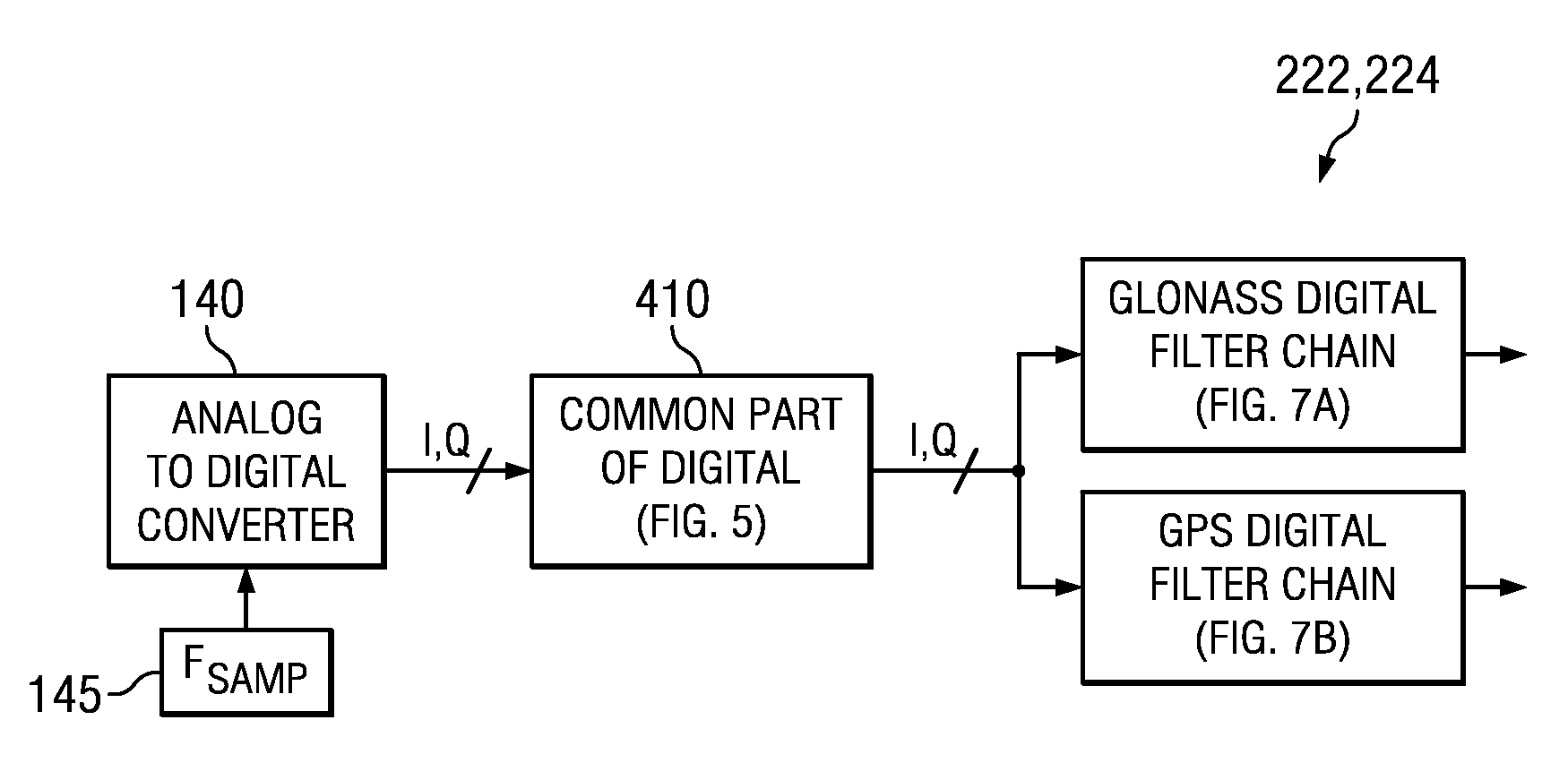
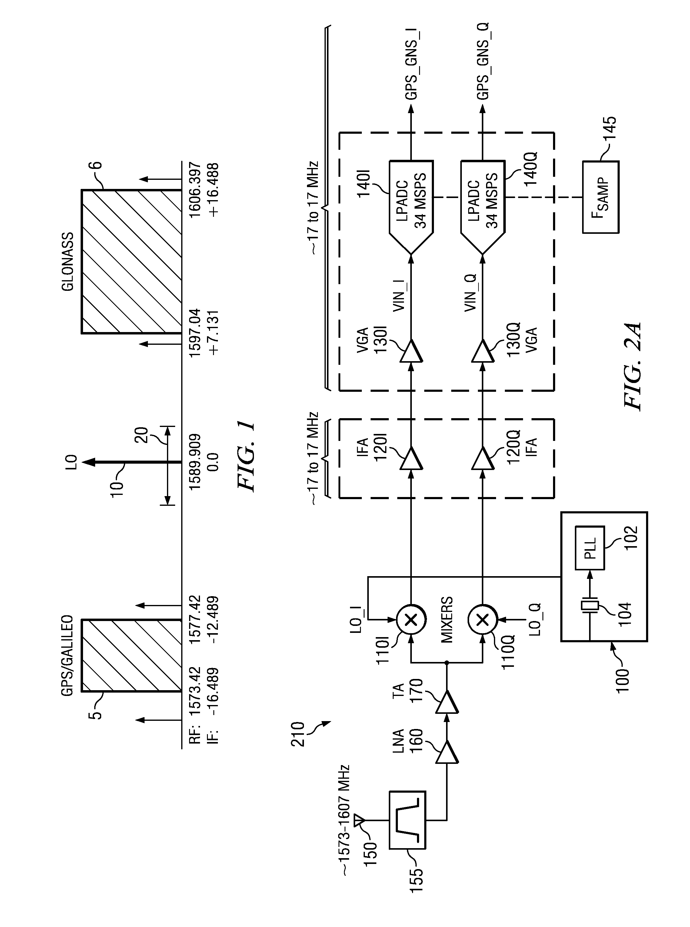
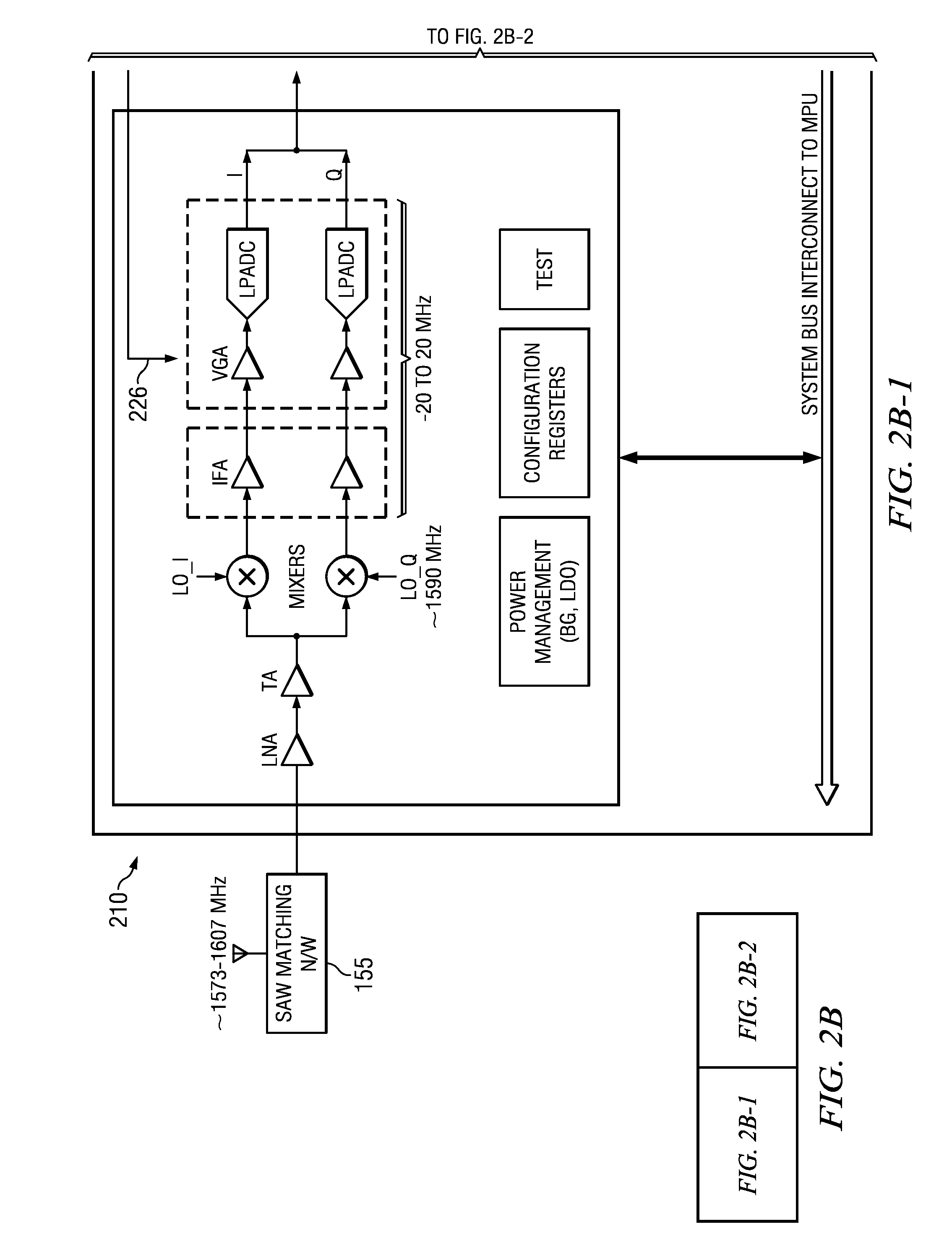
[0035]Some embodiments herein solve these problems and differentiate from prior art by introducing a single receive RF chain encompassing all of GPS, Galileo and Glonass at RF without significant image rejection with respect to heterodyning by a single LO situated in frequency between them, and followed by a single low power wide band IF encompassing all of GPS, Galileo and Glonass at IF, and further followed by software-based, hardware-based, or mixed digital signal processing to separate GPS, Galileo and Glonass in the IF from each other. Subsequent processing demodulates the information in respective satellite signals from any selected one, two or all of the GNSS either in parallel or consecutively, and electronically delivers time, position, velocity, and / or acceleration estimation and executes any other desired estimations and applications.

[0036]Changes are made in some embodiments to a conventional approach with multiple signal chains as follows:

1) Eliminate all but one signal...


PUM


Abstract

A wireless receiver for multiple frequency bands reception includes a single receive radio frequency (RF) circuit (160, 170) having an RF bandpass substantially confined to encompass at least two non-overlapped such frequency bands at RF, a single in-phase and quadrature (approximately I, Q) pair of intermediate frequency (IF) sections (120I, 120Q) having an IF passband, and a mixer circuit (110) including an in-phase and quadrature (I,Q) pair of mixers (110I, 110Q) fed by said RF circuit (160, 170) and having a local oscillator (100) with in-phase and quadrature outputs coupled to said mixers (110I, 110Q) respectively, said mixer circuit (110) operable to inject and substantially overlap the at least two non-overlapped frequency bands with each other into the IQ IF sections (120I, 120Q) in the IF passband, the IF passband substantially confined to a bandwidth encompassing the thereby-overlapped frequency bands. Other receivers, circuits.

Description

CROSS-REFERENCES TO RELATED APPLICATIONS[0001]This application is related to provisional India Patent Application “Single RF Receiver Chain Architecture for GPS, Galileo and Glonass Navigation Systems, and Other Circuits, Systems and Processes” 2131 / CHE / 2010, (TI-67884 IndiaPS), filed Jul. 27, 2010, for which priority is claimed under 35 U.S.C. 119 and all other applicable law, and which is incorporated herein by reference in its entirety.[0002]This application is related to U.S. Published Patent Application 20090054075, Feb. 26, 2009, “Satellite (GPS) Assisted Clock Apparatus, Circuits, Systems and Processes for Cellular Terminals on Asynchronous Networks,” of Ser. No. 11 / 844,006 (TI-38194), filed Aug. 3, 2007, which is incorporated by reference herein in its entirety.[0003]This application is related to U.S. patent application “Enhanced Cross Correlation Detection or Mitigation Circuits, Processes, Devices, Receivers and Systems” Ser. No. 12 / 719,965 (TI-67277), filed Mar. 9, 2010,...

Claims


Application Information

Patent Timeline
Patent Type & Authority Applications(United States)
IPC IPC(8): G01S19/33H04L27/06G01S19/37
CPCG01S19/33H04B1/0085G01S19/37
Inventor GANESHAN, SARAVANA KUMARBHUKANIA, BIJOYKANNAN, ANAND
Owner TEXAS INSTR INC
Why Eureka
Try Eureka