Optical sheet and light emitting device package having the same

Active Publication Date: 2012-02-02
SUZHOU LEKIN SEMICON CO LTD
View PDF5 Cites 42 Cited by
  • Summary
  • Abstract
  • Description
  • Claims
  • Application Information

AI Technical Summary

Benefits of technology

[0008]Therefore, embodiments provide an optical sheet, which enhances light efficiency an

Problems solved by technology

However, precipitation of the fluorescent substance may deteriorate uniformity of chromaticity and the fluorescent substance may be transformed due to heat generated from the L

Method used


Image

  • Optical sheet and light emitting device package having the same
  • Optical sheet and light emitting device package having the same
  • Optical sheet and light emitting device package having the same

Examples


Embodiment Construction

[0049]Prior to description of the embodiments, it will be understood that, when an element is referred to as being formed “on” or “under” another element, it can be directly “on” or “under” the other element or be indirectly formed with intervening elements therebetween. Further, “on” or “under” of each element will be described based on illustration in the drawings.

[0050]In the drawings, the size of each element is exaggerated, omitted or schematically illustrated for clarity and convenience of description. Therefore, the size of each element does not wholly reflect actual size thereof. Wherever possible, the same reference numbers will be used throughout the drawings to refer to the same or like parts.

[0051]Hereinafter, exemplary embodiments will be described in more detail with reference to the accompanying drawings.

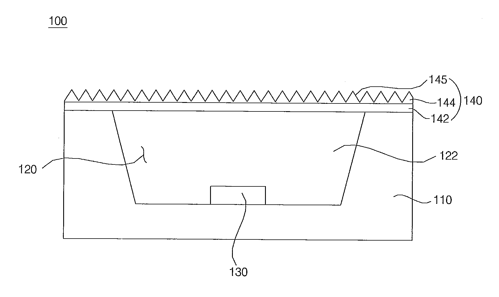
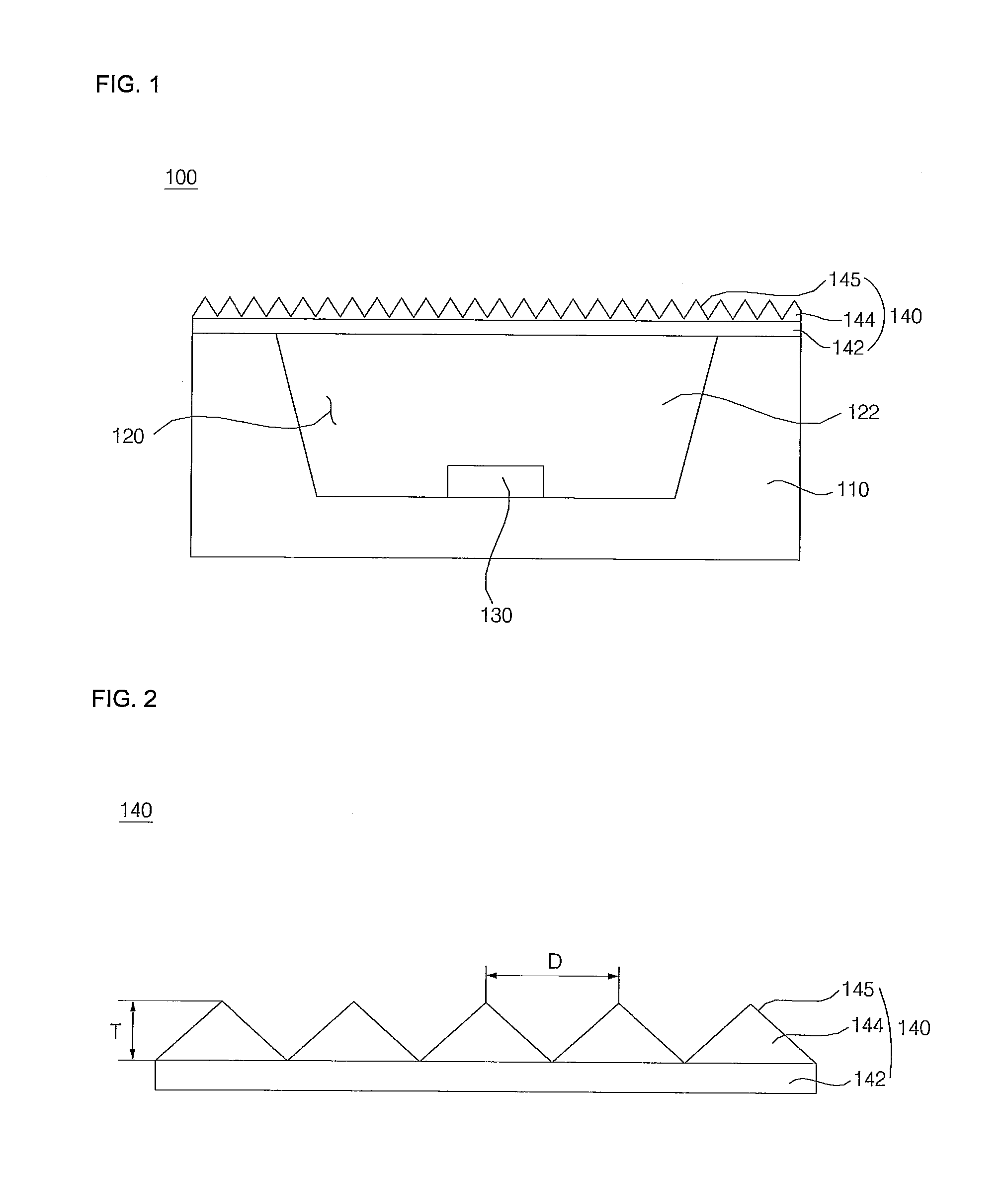
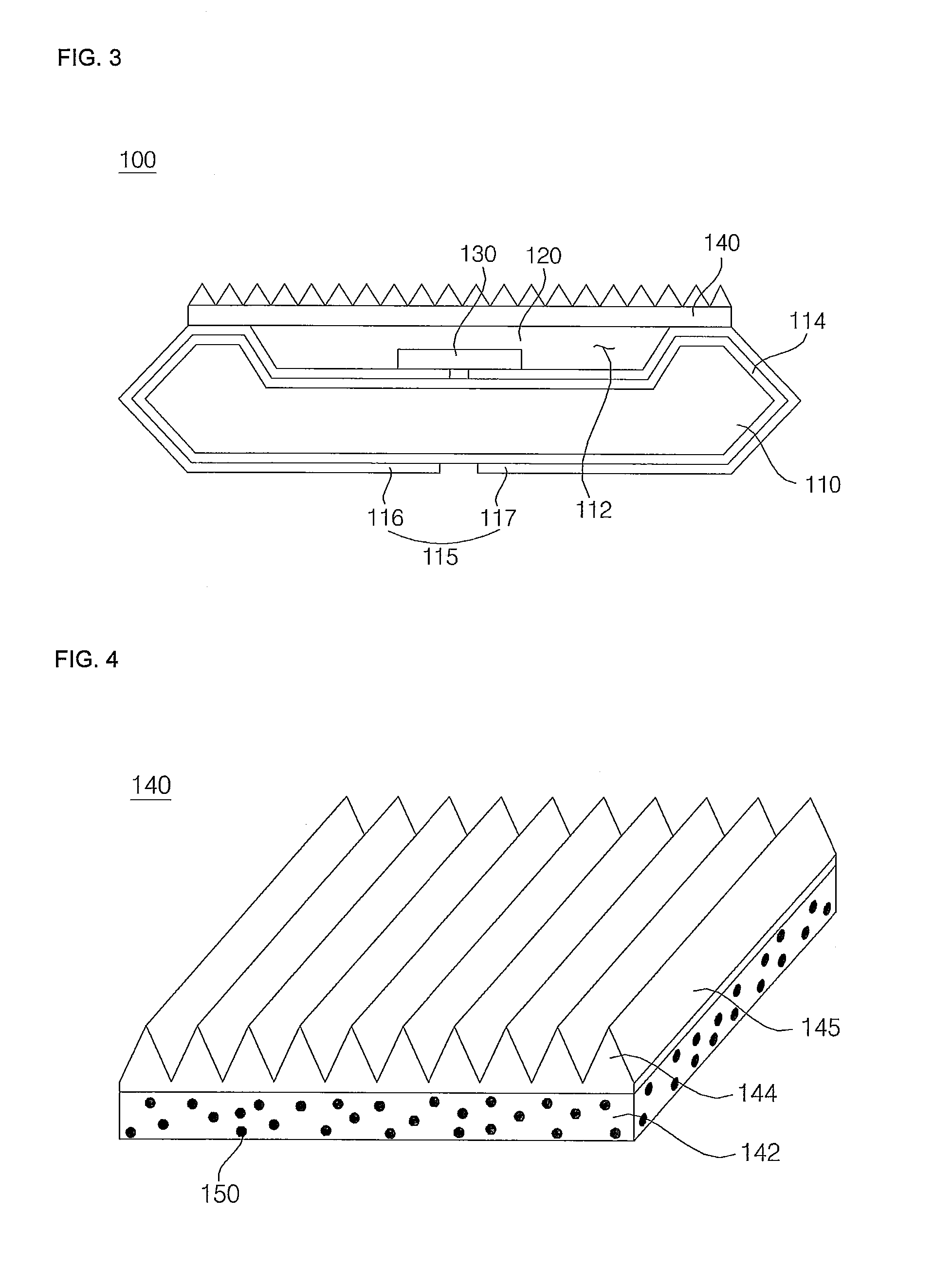
[0052]Referring to FIGS. 1 to 3, a light emitting device package 100 in accordance with an embodiment includes a body 110 having a cavity 120, a light source 130 moun...


PUM


Abstract

A light emitting device package is disclosed. The light emitting device package includes a body having a cavity, a light source mounted in the cavity, and at least one optical sheet located on the body to cover the cavity. The optical sheet includes a first layer and a second layer formed on the first layer, wherein the second layer includes a plurality of linear prism parts. At least one of the first layer and the second layer contains a light diffusive member. The light emitting device package has enhanced light emission efficiency and light distribution uniformity.

Description

CROSS-REFERENCE TO RELATED APPLICATION[0001]This application claims the priority benefit of Korean Patent Application No. 10-2010-0072998, filed on Jul. 28, 2010 in the Korean Intellectual Property Office, the disclosure of which is incorporated herein by reference.BACKGROUND[0002]1. Field[0003]Embodiments relate to an optical sheet and a light emitting device package having the same.[0004]2. Description of the Related Art[0005]Light Emitting Diodes (LEDs) are devices which convert electric signals into light using characteristics of compound semiconductors. Such LEDs are being utilized in home appliances, remote controllers, electric bulletin boards, displays and various other automated machines and the application range thereof is gradually increasing.[0006]Generally, miniature LEDs are fabricated into surface mount devices so as to be directly mounted on a Printed Circuit Board (PCB) and hence, an LED lamp, which serves as a display device, is being developed into a surface mount...

Claims


Application Information

Patent Timeline
IPC IPC(8): F21V9/16F21V11/00G02B5/02
CPCF21K9/17F21Y2101/02H01L2924/0002G02B5/0242G02B5/0278G02B5/045G02B6/0038G02B6/0041G02F2001/133607H01L33/50H01L33/58H01L2933/0091G02F1/133606G02F2202/046H01L2924/00F21K9/27F21Y2115/10F21K9/69G02F1/133607
Inventor CHO, BUMCHUL
Owner SUZHOU LEKIN SEMICON CO LTD
Why Eureka
Try Eureka