Lamp for laser applications

a laser and lamp technology, applied in the field of lamps, can solve the problems of limiting the brightness of such lamps, and achieve the effects of reducing heat accumulation, improving heat transport, and improving optical performan

Active Publication Date: 2012-02-02
SIGNIFY HLDG BV
View PDF5 Cites 68 Cited by
  • Summary
  • Abstract
  • Description
  • Claims
  • Application Information

AI Technical Summary

Benefits of technology

[0006]It is the object of the invention to provide a possibility to improve optical performance in laser applications in conjunction with solving the thermal issue problem mentioned above in order to mitigate heat accumulation in a fluorescent body and thus to improve heat transport through a transparent body which comprises the fluorescent body.
[0009]It is noted that the transparent body is also called holder in the following. It is an important idea of the invention that it becomes possible to improve heat transport through the holder.
[0017]It is worth noting that the invention provides a lamp adapted for generating light comprising a source, such as a semiconductor light emitting element, preferably an LED, or a laser, a fluorescent body is substantially embedded in a transparent body and is provided away from the source, such that the lamp shows a high optical performance. The focusing unit is preferably adapted for focusing light or optical radiation generated by the source onto the fluorescent body. According to another preferred embodiment of the invention, the focusing unit is adapted for focusing light or optical radiation generated by the source through the holder. It is advantageous that the holder is attached to the fluorescent body, such that this arrangement comprises a good thermal interface corresponding to a low thermal contact resistance. The attachment between holder and fluorescent body is preferably achieved by melting glass, ceramic glue, more preferably by transparent pressure ceramic or silicon thermal interface material. The fluorescent material preferably comprises a Lumiramic material, characterized by an efficient and high light conversion, a high thermal conductivity, such as k>6 W / mK at room temperature, a high thermal stability and / or highly scattering visible light. It is noted that, according to a preferred embodiment of the invention, the fraction of the laser power dissipated in the fluorescent body comprises a value≧300 mW, more preferably≧800 mW and most preferably≧1.3 W.
[0019]It is worth noting that by scanning the fluorescent body with the optical radiation emitted by the source or by dynamically adjusting the scan area and / or the focus of the lamp spot, a dynamic tunable light spot can be achieved. According to another preferred embodiment of the invention, the focusing unit is preferably adapted for bending and / or for scanning the light generated by the source. Preferably, the lamp is adjustable to excite fluorescent emission over various parts or lengths of the fluorescent material. Thereby, different beam shapes can be realized. Most preferably, the filament shaped Lumiramic emitter comprises a plurality of segments, wherein each segment comprises a length of about 300 μm to 1 mm. In other words, a segmented luminescent body and / or a scanning laser beam are preferably used to realize a lamp adapted for generating a variable beam width. Therefore, while using a relatively simple mechanical setup different beam shapes adapted for different applications are realizable.
[0020]A segmented Lumiramic emitter arranged on an optical axis of a reflector comprising a parabolic shape, a Bezier type shape or any other shape can advantageously be used. The filament shaped Lumiramic emitter preferably comprises a plurality of segments, the plurality of segments being preferably separated by a highly scattering material, such as titanium dioxide, adapted for preventing optical cross talk between the plurality of segments. These segments can be connected by melting glass, ceramic glue or other techniques. In this way damaging by high power density of a laser can be countervailed. Each segment of the plurality of segments is preferably excited individually which is adapted for emitting visible light by a blue or UV pump laser. According to another preferred embodiment of the invention, white light is emitted.

Problems solved by technology

Very local heat dissipation in the fluorescent material appears and thus limits the brightness of such a lamp.

Method used


Image

  • Lamp for laser applications
  • Lamp for laser applications
  • Lamp for laser applications

Examples


Embodiment Construction

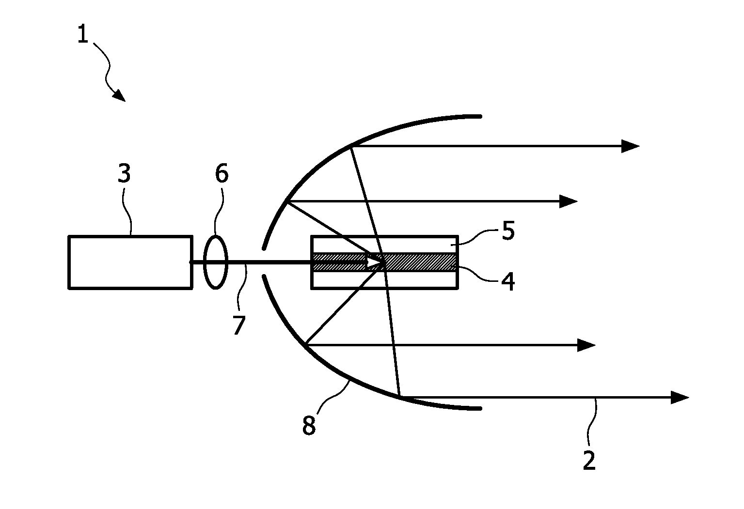
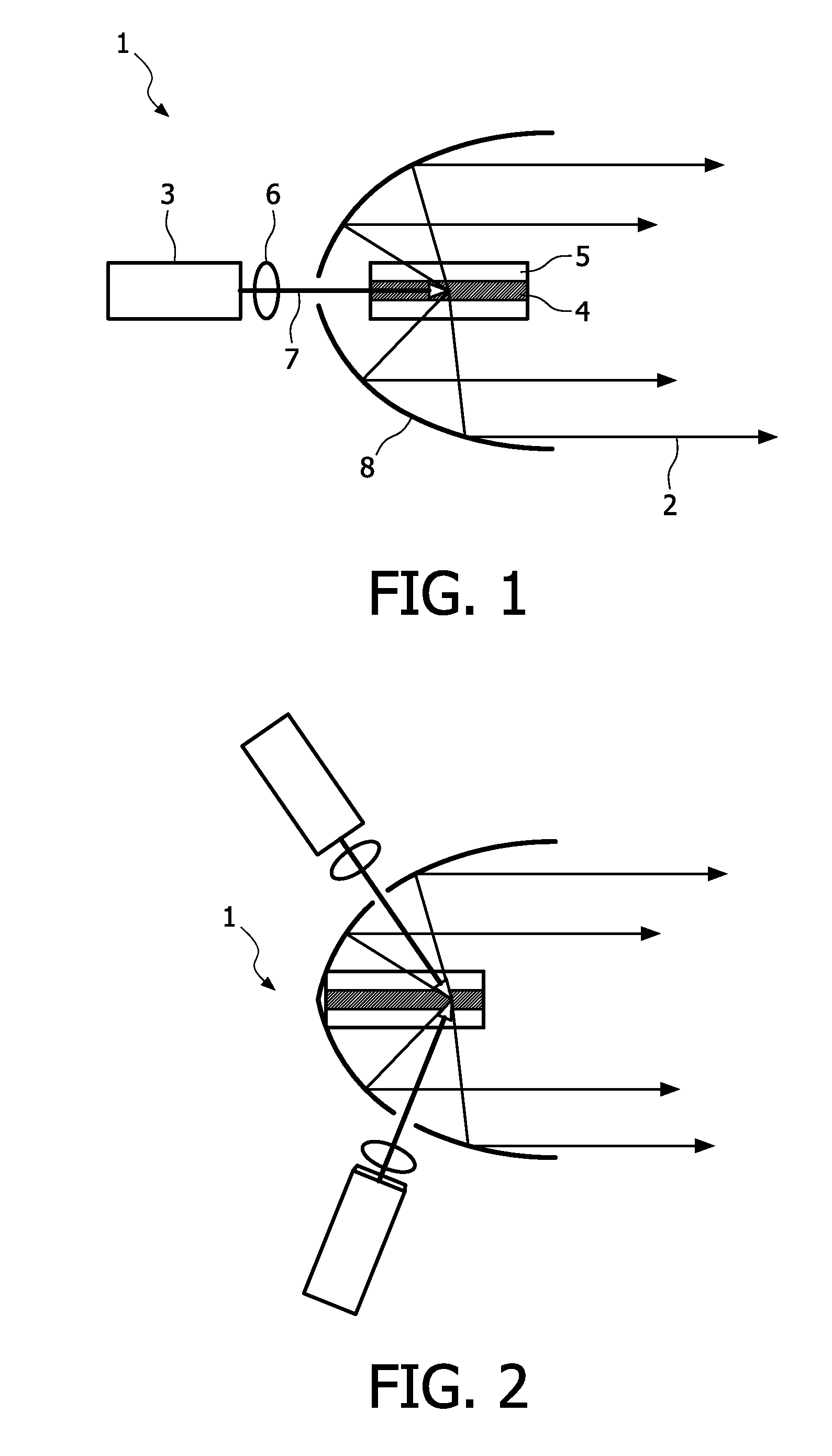
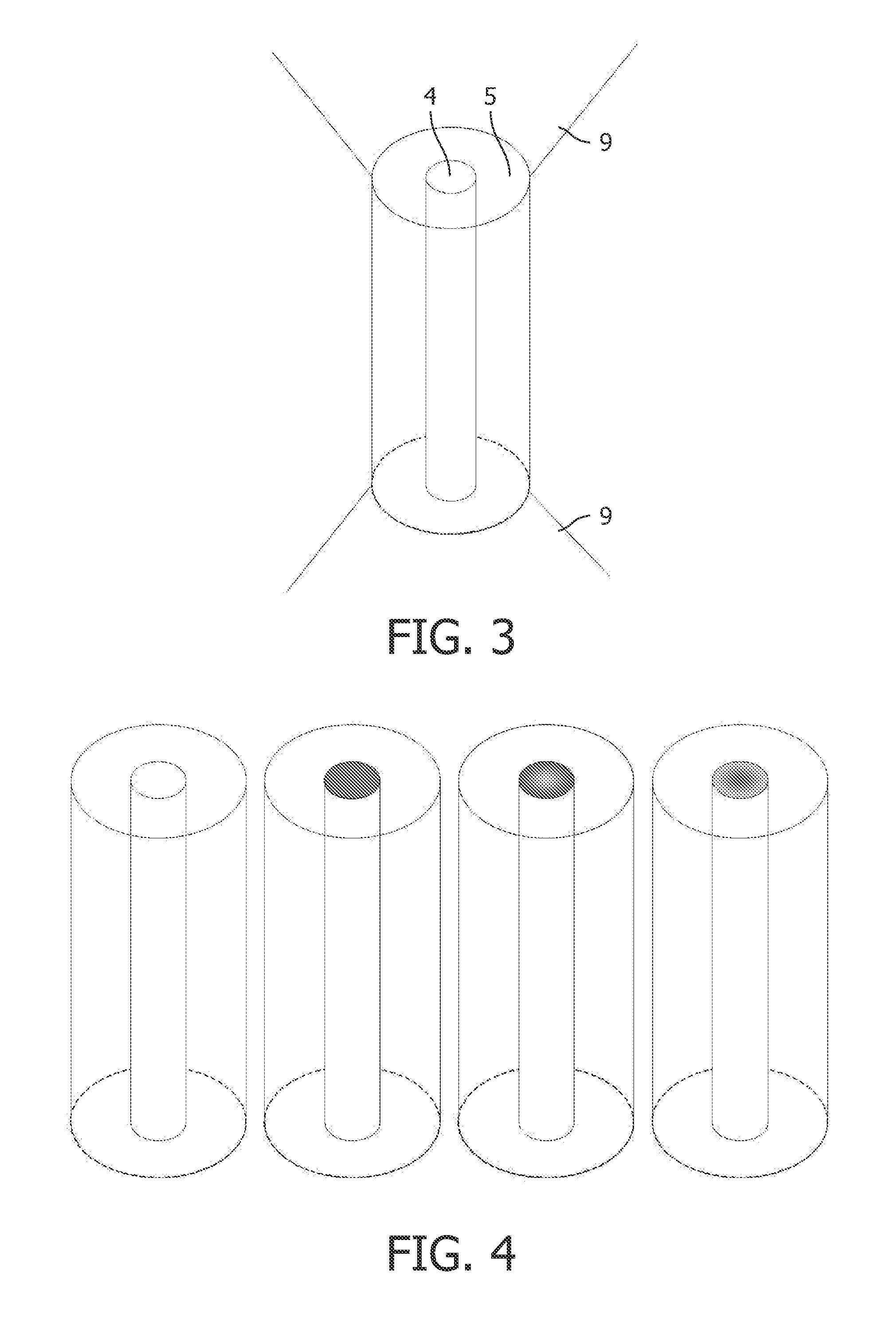
[0035]FIG. 1 schematically illustrates a laser pumped lamp 1 according to a first preferred embodiment of the invention. The lamp 1 generates radiation. i.e. light 2, and comprises a source 3. A fluorescent body 4 is substantially embedded in a holder 5, wherein the holder 5 corresponds to a transparent body, and is provided away from the source 3. The source 3 is adapted for emitting optical radiation along an optical path and the holder 5 comprises the fluorescent body 4, wherein the holder 5 is arranged in the optical path. A collecting unit 8 is provided which is adapted for transmitting at least a portion of optical radiation emitted by the fluorescent body 4 to an output of the lamp 1. According to the first preferred embodiment of the invention, the collecting unit 8 corresponds to a parabolic reflector. As can be seen from FIG. 1, the fluorescent body 4 comprises a shape being elongated in a predetermined direction. According to the first preferred embodiment of the inventio...


PUM


Abstract

The invention relates to a lamp and a method, preferably adapted for generating high power in laser applications. The lamp (1) comprises a source (3) adapted for emitting optical radiation along an optical path and a holder (5) comprising a fluorescent body (4), wherein the holder (5) is arranged in the optical path, a collecting unit (8) is provided which is adapted for transmitting at least a portion of optical radiation emitted by the fluorescent body (4) to an output of the lamp (1), and the fluorescent body (4) comprises a shape being elongated in a predetermined direction. In this way, a small spot and little divergence is provided in conjunction with good heat dissipation leading to a high optical performance.

Description

FIELD OF THE INVENTION[0001]The invention relates to the field of lamps adapted for laser applications. The invention also relates to the field of methods adapted for laser applications. The invention is preferably adapted for high power laser applications and / or for lighting applications.BACKGROUND OF THE INVENTION[0002]U.S. Pat. No. 7,165,871 B2 describes a lamp for generating light which comprises a semiconductor light emitting element for emitting light, a fluorescent material, provided away from the semiconductor light emitting element, a first optical member operable to focus the light generated by the semiconductor light emitting element on the fluorescent material, and a second optical member having an optical center at a position where the fluorescent material is provided, operable to emit light from the fluorescent material based on the light focused by the optical member to an outside of the lamp. The lamp is used as a headlamp in a vehicle, and the second optical member ...

Claims


Application Information

Patent Timeline
Patent Type & Authority Applications(United States)
IPC IPC(8): F21K2/00F21V9/40
CPCC09K11/08F21K9/56F21S48/115F21V9/16F21Y2101/02F21Y2101/025H01L2924/0002G02B6/0003H01L33/50F21S48/328H01L2924/00F21K9/64F21Y2115/30F21Y2115/10F21S41/321F21S45/47F21S41/16F21V9/30F21S41/336F21V13/08F21S41/176F21S41/141F21S41/14
Inventor KURT, RALPHDRENTEN, RONALD REINDERTPAULUSSEN, ELVIRA JOHANNA MARIAVALSTER, ADRIAANFOURNIER, DENIS
Owner SIGNIFY HLDG BV
Why Eureka
Try Eureka