Infusion Reservoir With Push-On Connector Features And/Or Attachments Therefor

a technology of push-on connectors and reservoirs, which is applied in the direction of manufacturing tools, intravenous devices, metal working apparatuses, etc., can solve the problems of inability to fully meet the abilities of users, adversely affect the dosing and programmable delivery schedule, and require user actions or motions. to achieve the effect of maintaining function and maximizing ease of us

Active Publication Date: 2012-02-02
BECTON DICKINSON & CO
View PDF5 Cites 73 Cited by
  • Summary
  • Abstract
  • Description
  • Claims
  • Application Information

AI Technical Summary

Benefits of technology

[0011]An object of the present invention is to substantially solve the above and other problems and difficulties, and provide reservoir designs, constructions and implementations to adapt to different configurations of infusion pumps and line sets that may be encountered, maximize ease of use, while also maintaining function.
[0012]Another object of the present invention is to provide line set designs, constructions and implementations to adapt to different configurations of infusion pumps, connectors and reservoirs that may be encountered, maximize ease of use, while also maintaining function.
[0013]Another object of the present invention is to provide straight-line, push-on type connector designs, constructions and implementations to adapt to different configurations of infusion pumps, reservoirs and line sets that may be encountered, maximize ease of use, while also maintaining function.
[0014]Another object of the present invention is to provide reservoir designs, constructions and implementations to adapt to different configurations of infusion pumps, connectors and line sets that may be encountered, maximize ease of use, while also maintaining function.
[0015]Another object of the present invention is to provide straight-line, push-on type connector designs, constructions and implementations to releasably secure a reservoir within any number of infusion pump body configurations using only a simple, straight-line push-on motion.
[0017]Another object of the present invention is to provide straight-line, push-on type connector designs, constructions and implementations to allow coupling of a custom Luer fitting with a reservoir releasably secured within any number of infusion pump body configurations and prevent coupling of a standard Luer fitting with the reservoir.

Problems solved by technology

The initial cost of the pump can be significant, but from a user perspective, the overwhelming majority of patients who have used pumps prefer to remain with pumps for the rest of their lives.
However, patients may encounter situations wherein different configurations of infusion pumps, reservoirs and line sets are required for one or more reasons, and such patients may become concerned that the different configurations could adversely affect dosing and programmable delivery schedules.
Plus, many current systems and methods require user actions or motions not fully compatible with each user's abilities.
The human factors are not intuitive with this second operation, and there is a tendency to unscrew the line connection from the reservoir.
Another failure that could occur in such a system and method is the separation of the line from the Luer connector, again resulting in insulin leakage from the line.
In such a system and method, the user motions necessary to place the reservoir into the pump reservoir cavity and complete the engagement of the line set connection are excessive and not intuitive, and the separate threaded sleeve is akin to a wear component requiring periodic replacement.
However, the user may not always know when the sleeve requires replacement and failure to replace the sleeve could result in contamination from the worn elastomer migrating into the pump reservoir cavity or loss of ability to properly engage and torque the separate threaded sleeve.
Still further, the separate threaded sleeve could also be lost or misplaced, since it is not an integral part of either the reservoir, line set or pump.
However, removal of the O-ring can be difficult for some users with limited dexterity, and improper removal of the O-ring can result in O-ring contamination migrating into the pump reservoir cavity or depending on the O-ring removal tool, can result in damage to the O-ring groove which retains the O-ring in the pump reservoir cavity.
Ultimately, this damage can impact dosing or pump performance.
Further, O-ring wear can occur which may not be noticeable to the user, causing O-ring particulates to enter the pump reservoir cavity or loss of sealing capabilities of the O-ring and migration of contaminates into the pump reservoir cavity.
Accordingly, many components of such systems cannot be interchanged.

Method used


Image

  • Infusion Reservoir With Push-On Connector Features And/Or Attachments Therefor
  • Infusion Reservoir With Push-On Connector Features And/Or Attachments Therefor
  • Infusion Reservoir With Push-On Connector Features And/Or Attachments Therefor

Examples


third embodiment

[0123]Further, the third embodiment illustrates an example of a fault ring indicator 406 that can be applied to any exemplary embodiment, and which remains exposed around a portion of the expander sleeve that would normally be engaged within the reservoir opening. In doing so, the fault ring indicator 406 can be provided to illustrate when the expander sleeve is not fully seated and therefore, the reservoir is not secured. When the expander sleeve has been fully seated, the fault ring indicator 406 is hidden within the reservoir opening. In an exemplary embodiment of the present invention, the fault ring indicator can be a band, mark or O-ring, and made in a bright color, such as red or orange, but is not limited thereto.

[0124]FIGS. 13-15 are additional views of the third embodiment further illustrating the fault ring indicator or mark showing an unseated expander sleeve 403 in a position when the reservoir is first placed into the pump reservoir cavity and the expander sleeve 402 i...

fourth embodiment

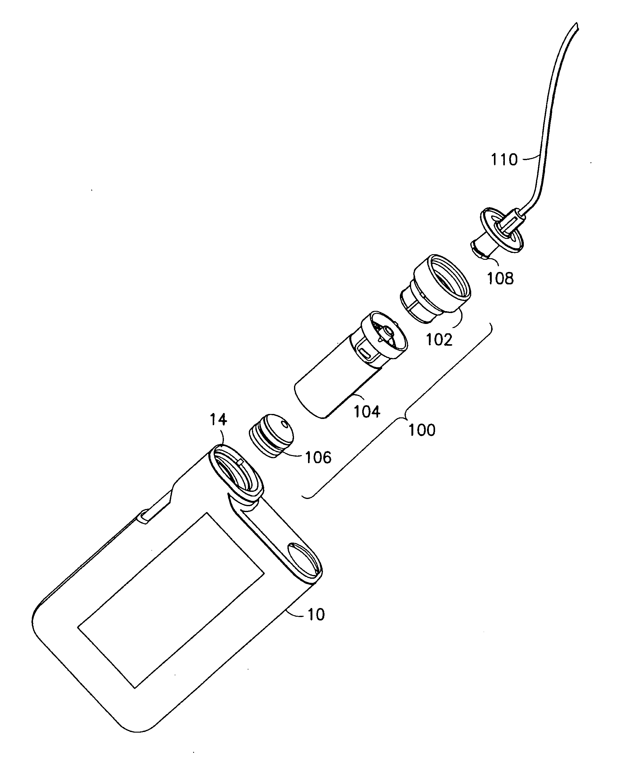
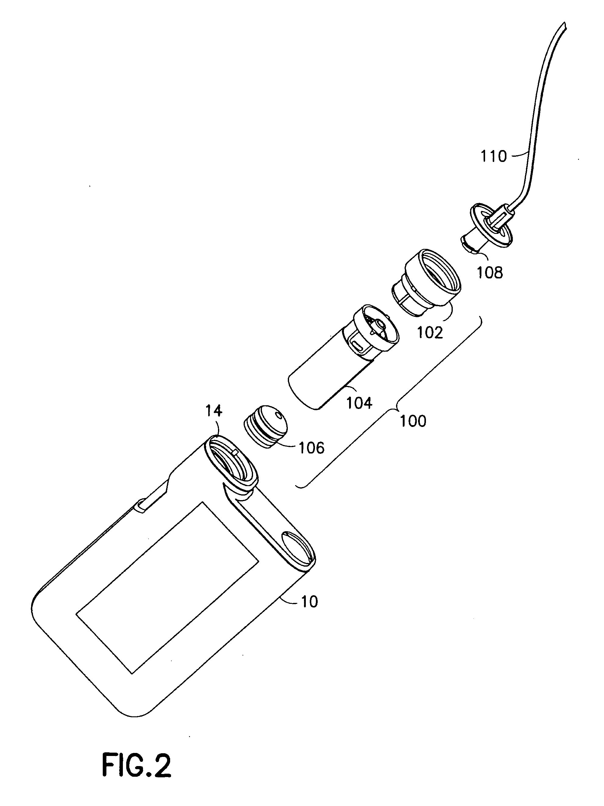
[0125]In this or other exemplary embodiments of the present invention, an integrated guide can be designed and provided to target a desired alignment of the assembly as the reservoir and straight-line, push-on connector assembly are engaged into the pump reservoir cavity. FIG. 16 is an exploded view of a fourth exemplary embodiment of such an alignment guide, reservoir, and straight-line, push-on connector assembly for interfacing a line set with the infusion pump of FIG. 1 in accordance with an embodiment of the present invention, and FIGS. 17 and 18 are views of the fourth embodiment inserted with the infusion pump of FIG. 1.

[0126]In the exemplary embodiment, an expander sleeve 480 is further configured to provide an integrated guide for insertion of the reservoir. Since the expander sleeve is preferably retained by the reservoir, the integrated guide 480 of the fourth embodiment is configured to orient the reservoir relative to the top and side surfaces of the infusion pump 10 du...

fifth embodiment

[0130]FIGS. 22 and 23 are views of an assembled “armless” reservoir and straight-line, push-on connector assembly. The pieces 608 and 610 are positioned within openings 612 and 614 in the reservoir 602, and are urged outward from the openings 612 and 614 by the insertion of the expander sleeve 606 into the reservoir 602. Once urged outward in such a manner, the pieces 608 and 610 perform substantially as described above in regard to embodiments one to five.

[0131]The exemplary embodiment shown in FIGS. 19-23 illustrates another example of the positioning of a hydrophobic membrane on the grasping diameter of the expander sleeve 606. In this case, the hydrophobic membrane covered openings 620 provide a pathway for air ingress and egress, and a flat surface is provided on an inner surface of the expander sleeve 606 on which to attach the hydrophobic membrane. As noted above, such exemplary features are easily moldable, and the hydrophobic membrane can be heat staked or bonded with UV cu...


PUM

PropertyMeasurementUnit
hydrophobicaaaaaaaaaa
outer diameteraaaaaaaaaa
flexibleaaaaaaaaaa

Abstract

A reservoir and straight-line, push-on connector assembly is provided for connecting the reservoir and one of a standard Luer line set and a custom Luer line set to any number of infusion pump configurations using a simple straight-line, push-on motion, wherein the push-on connector assembly is provided and configured to secure the line set and reservoir with the infusion pump. One simple straight-line, push-on motion, preferably performed by gripping an expander sleeve, places and secures the reservoir (i.e., locates the reservoir on the x, y, and z axes) in the pump reservoir cavity, and one simple straight-line, pull-off motion releases and removes the reservoir from the pump reservoir cavity. Rotational orientation is not required for connection, pump engagement, or pump function, and any pulling of the tube set will not release the reservoir as the expansion sleeve through which the tube set is routed is not moved from the securing position by tension on the tube set or Luer fitting.

Description

CROSS-REFERENCE TO RELATED APPLICATIONS[0001]This application claims the benefit under 35 U.S.C. §119(e) of a U.S. provisional patent application of Charles Hwang et al. entitled “Infusion Reservoir With Push-On Connector Features and / or Attachments Therefor”, Ser. No. 61 / 369,706, filed on Jul. 31, 2010, the entire content of said application being incorporated herein by reference.FIELD OF THE INVENTION[0002]The present invention relates generally to components and elements of infusion systems, including a push-on connector and reservoir assembly for connecting the reservoir and line set to any number of infusion pump configurations using a simple straight-line push-on motion.BACKGROUND OF THE INVENTION[0003]A large number of people, including those suffering from conditions such as diabetes use some form of infusion therapy, such as daily insulin infusions to maintain close control of their glucose levels. There are currently two principle modes of daily treatment for insulin infus...

Claims


Application Information

Patent Timeline
Patent Type & Authority Applications(United States)
IPC IPC(8): A61M5/142B23P17/04
CPCA61M5/14248A61M5/385Y10T29/49826A61M2039/1027A61M2005/14573
Inventor HWANG, CHARLESSEARLE, GARY
Owner BECTON DICKINSON & CO
Why Eureka
Try Eureka