Supervisory control method and equipment for smart grids
- Summary
- Abstract
- Description
- Claims
- Application Information
AI Technical Summary
Benefits of technology
Problems solved by technology
Method used
Image
Examples
Example
[0041]Modes for carrying out the present invention are described below with reference to the drawings.
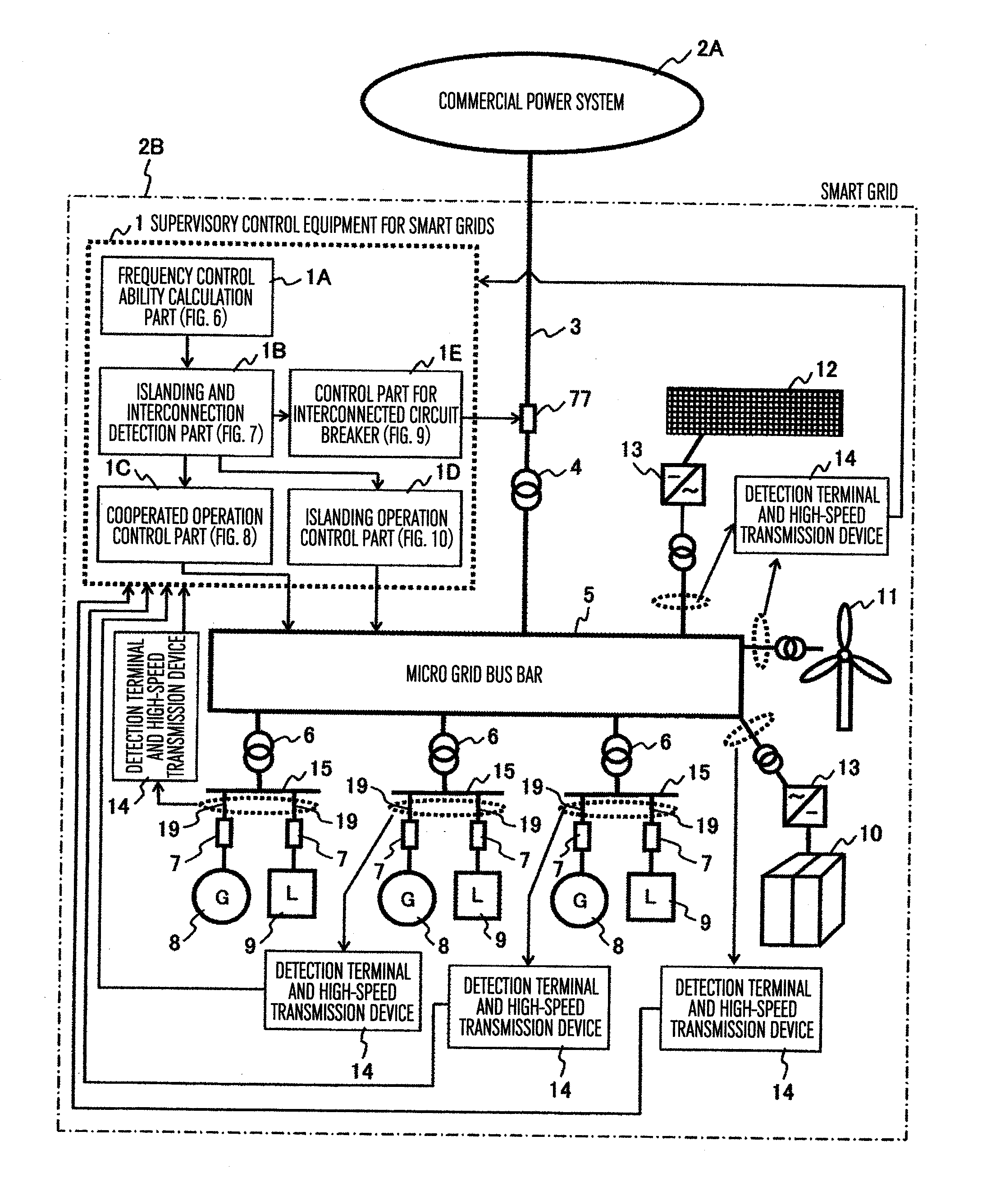
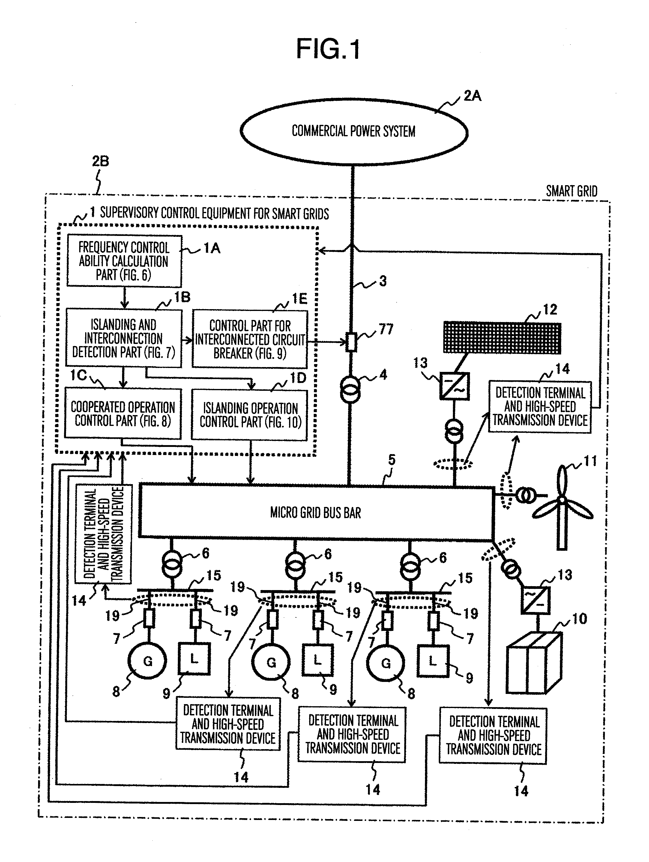
[0042]FIG. 1 shows a whole structure of a power system configuring a smart grid and its supervisory control equipment 1.
[0043]The power system configuring a smart grid 2B is described. The smart grid 2B has a smart grid bus bar 5, which can be connected to a commercial power system 2A through an interconnected transformer 4, an interconnected circuit breaker 77, and an interconnected transmission line 3. As the smart grid bus bar 5, a loop structure, a mesh structure or a radial structure is conceived, but FIG. 1 shows an example of the loop structure.
[0044]The smart grid bus bar 5 is connected with plural power sources and loads. As the power sources, for example, plural generators 8 are disposed and connected to the smart grid bus bar 5 through a circuit breaker 7, a generator bus bar 15, and a generator transformer 6. And loads 9 are connected to the generator bus bars 15 through...
PUM
 Abstract
Description
Claims
Application Information
 - R&D
- Intellectual Property
- Life Sciences
- Materials
- Tech Scout
- Unparalleled Data Quality
- Higher Quality Content
- 60% Fewer Hallucinations
Browse by: Latest US Patents, China's latest patents, Technical Efficacy Thesaurus, Application Domain, Technology Topic, Popular Technical Reports.
© 2025 PatSnap. All rights reserved.Legal|Privacy policy|Modern Slavery Act Transparency Statement|Sitemap|About US| Contact US: help@patsnap.com


