Dynamic electric power line monitoring system

a monitoring system and electric power technology, applied in the field of electric power lines, can solve problems such as providing a false sense of security, and achieve the effect of facilitating the construction of new networks

Active Publication Date: 2012-02-02
LINDSEY MFG
View PDF8 Cites 38 Cited by
  • Summary
  • Abstract
  • Description
  • Claims
  • Application Information

AI Technical Summary

Benefits of technology

[0010]Better management of transmission line sag promotes more efficient use of existing electrical distribution networks, thus forestalling the building of new networks.

Problems solved by technology

This approximation, however, can provide a false sense of security.

Method used


Image

  • Dynamic electric power line monitoring system
  • Dynamic electric power line monitoring system
  • Dynamic electric power line monitoring system

Examples


Embodiment Construction

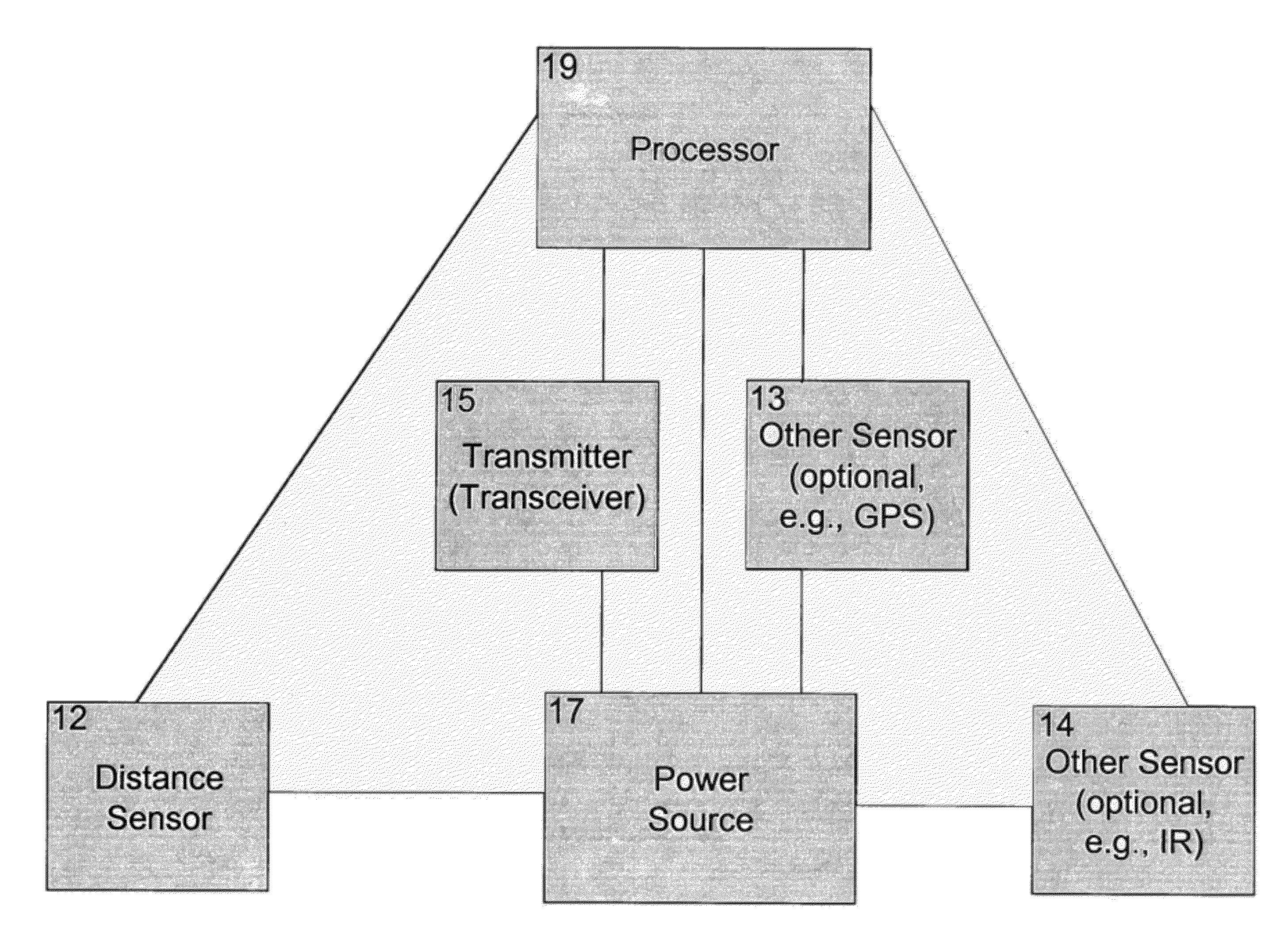
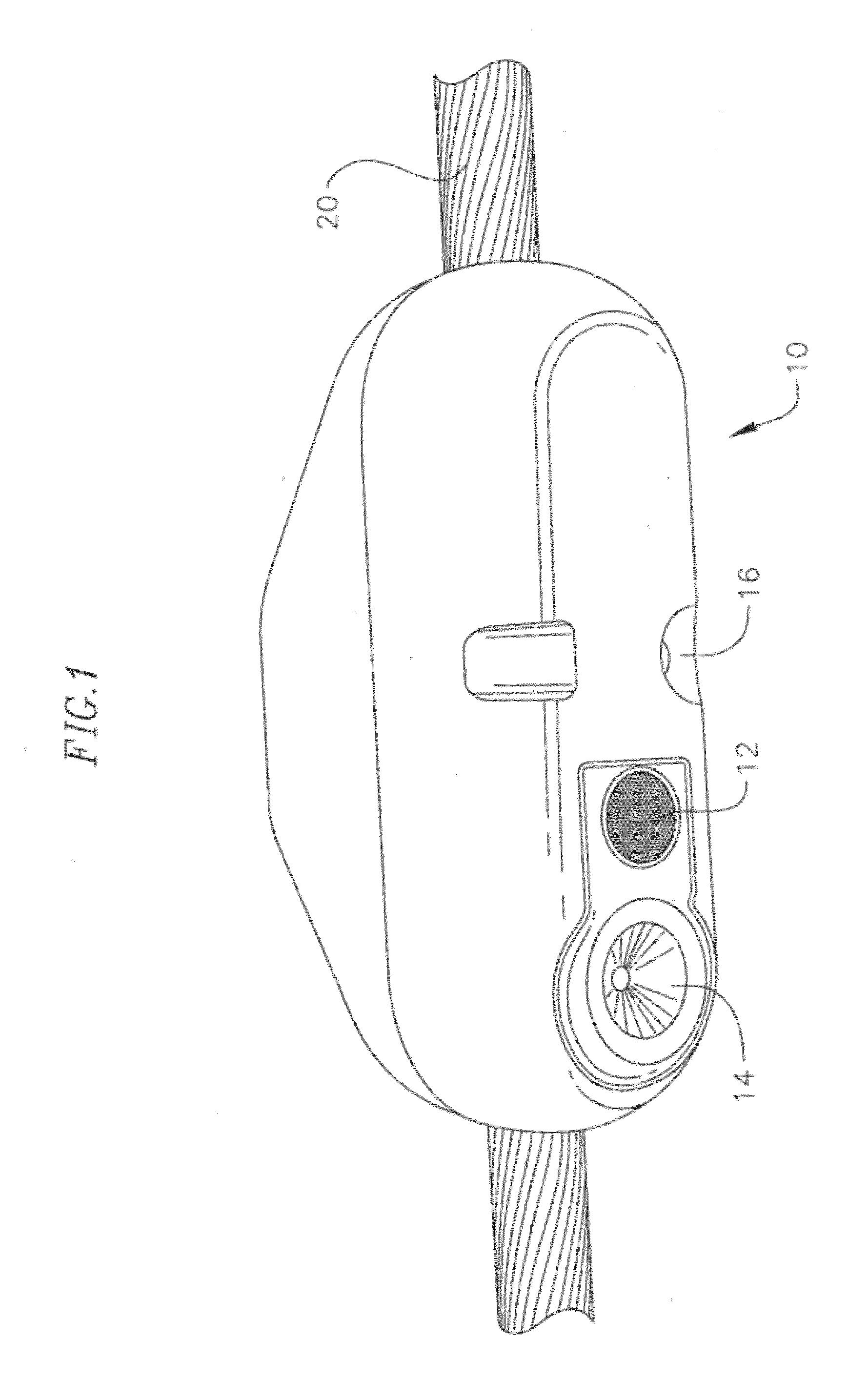
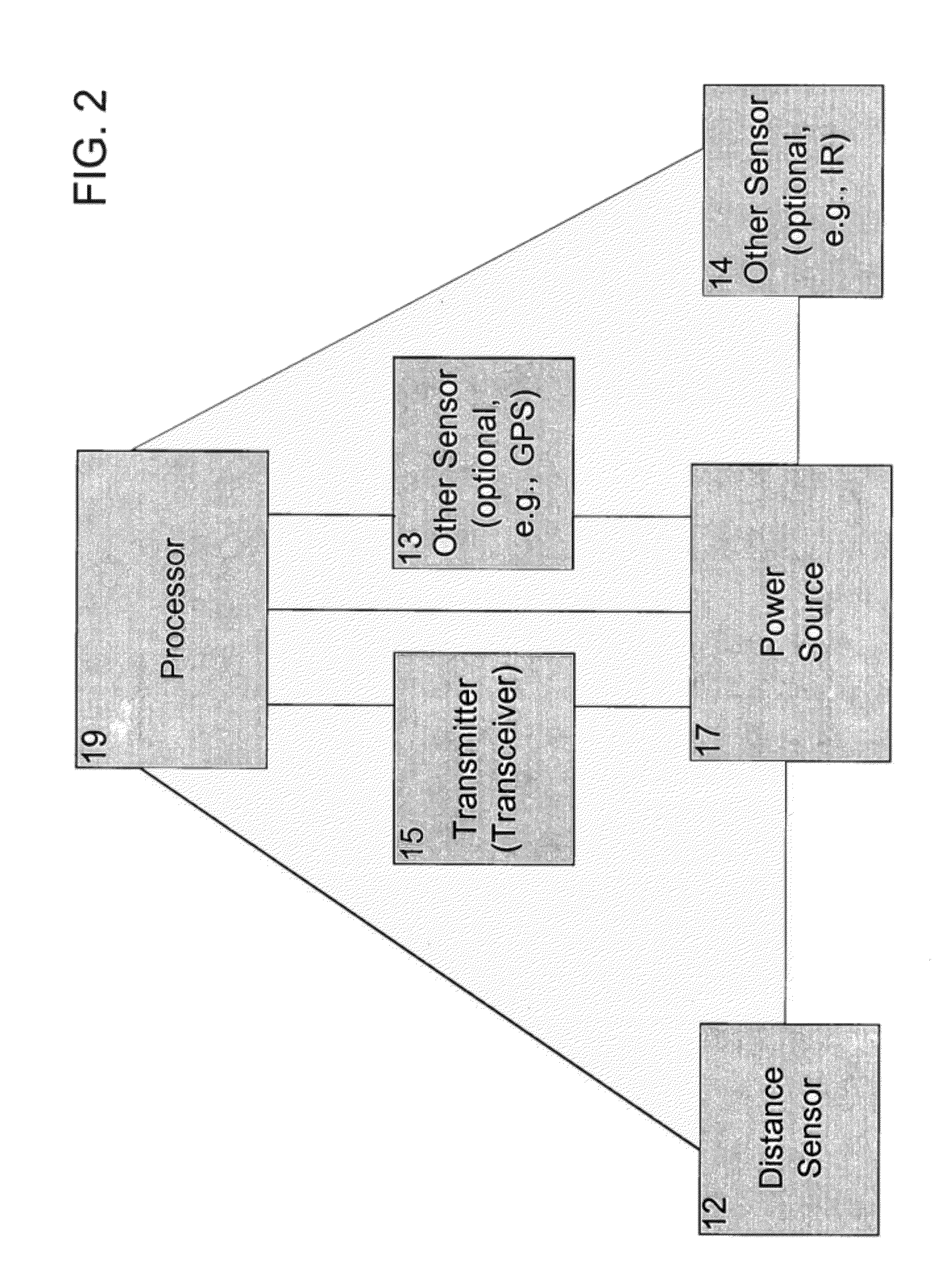
[0037]The illustrative embodiments that follow are only exemplary applications of the present invention and not intended to limit the scope of the invention. For example, while the embodiments may be directed to electrical transmission lines, there is nothing to prevent other embodiments from being directed to electrical distribution lines, or to any type of electrical power line. Further, while embodiments may be directed at detecting the sag (for example, the distance to the nearest object below an electrical line), there is nothing to prevent other embodiments from being directed to detecting the proximity of an object (for example, a neighboring transmission line) located to the side of the transmission line, or anywhere else in relation to the transmission line. Still other embodiments may be directed to other electric power line monitoring (for example, temperature, motion, etc.) or monitoring from the electric power line, using a network (mesh) of transceiver-equipped monitor...


PUM


Abstract

A device and method of precise distance measurement of a transmission line to any object below it is disclosed, along with a network of such devices. The technique employs ultrasonic sensor technology to measure the distance to the nearest object, be it vegetation or a crossing conductor below, and reports that distance wirelessly to the system operator or transmission asset owner. The ultrasonic measurement package may be part of a Transmission Line Security Monitor, which mounts to a transmission line conductor and is powered by the transmission line, transmitting the data by radio links. The technology is equally applicable to encroachment of objects from the side (for example, other transmission lines), as well as to other electrical lines, such as distribution lines, or to other sensing. A built-in transceiver allows the device to communicate with other devices and forward alerts from these devices in a daisy-chain fashion to the intended recipient.

Description

BACKGROUND[0001]1. Field[0002]Aspects of the present invention relate to the field of electric power lines. More specifically, aspects of the present invention relate to the field of monitoring from electric power lines.[0003]2. Description of the Related Art[0004]As a transmission line is pushed to carry more energy, the conductor heats and, because of the added heat, the transmission line sags. The traditional method of determining the conductor sag has been derived by a set of operating conditions. For example, knowing the conductor's physical size, its manufacturer's rated current capacity, current flow, the approximate still air ambient temperature, wind speed, and time of day, the system operator could “approximate” how much the conductor sags.[0005]This approximation, however, can provide a false sense of security. For instance, the Northeast Blackout of 2003 was the result of an overloaded transmission line flashing over to ground by sagging into vegetation below the transmi...

Claims


Application Information

Patent Timeline
Patent Type & Authority Applications(United States)
IPC IPC(8): G06F15/00G01B21/16G01B17/00
CPCG01S7/003G01S15/08H02G1/02G06F17/00G01B13/12G01B17/00G01K1/024H02G7/00H04Q2209/40H04Q2209/43H04Q2209/25H04Q9/00H04Q2209/823H04Q2209/88
Inventor SPILLANE, PHILIP E.
Owner LINDSEY MFG
Why Eureka
Try Eureka