
PCI express tlp processing circuit and relay device provided with this

a relay device and processing circuit technology, applied in the field of pci express devices, can solve the problem that errors cannot be detected at the reception destination of tlps

Inactive Publication Date: 2012-02-02
KK TOSHIBA
View PDF6 Cites 12 Cited by
  • Summary
  • Abstract
  • Description
  • Claims
  • Application Information

AI Technical Summary

Benefits of technology

[0055]According to the present invention, a PCI Express TLP processing circuit and a relay device provided there with can be provided whereby data integrity can be guaranteed by detecting an error in data transmitted from a relay device.

Problems solved by technology

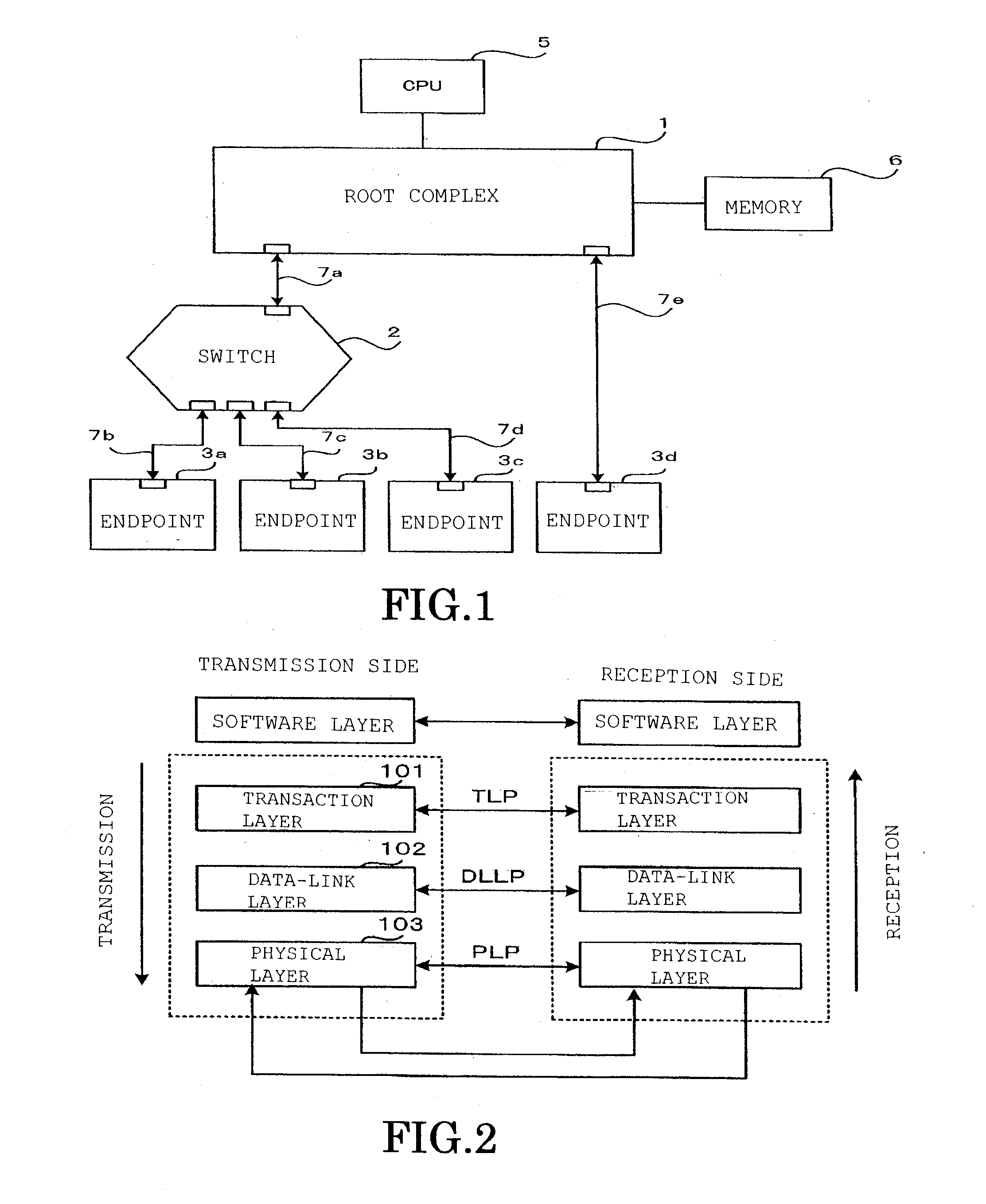
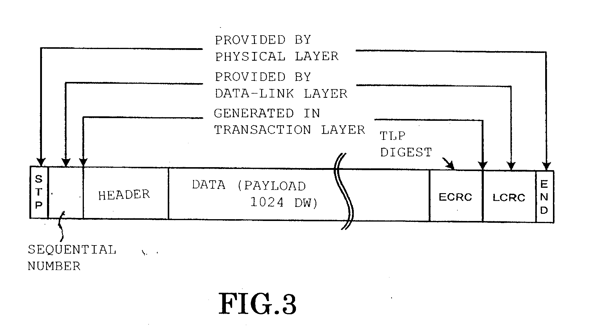
Consequently, if reliance for data error detection is placed exclusively on the LCRC function, there is the problem that, if an error is generated in the data of a TLP in a relay circuit (in this case, any circuit that is located above the data-link layer is termed a relay circuit) of the switch or the root complex, since an LCRC including this error is generated normally, this error cannot be detected at the reception destination of the TLP.

Method used


Image

  • PCI express tlp processing circuit and relay device provided with this
  • PCI express tlp processing circuit and relay device provided with this
  • PCI express tlp processing circuit and relay device provided with this

Examples


embodiment

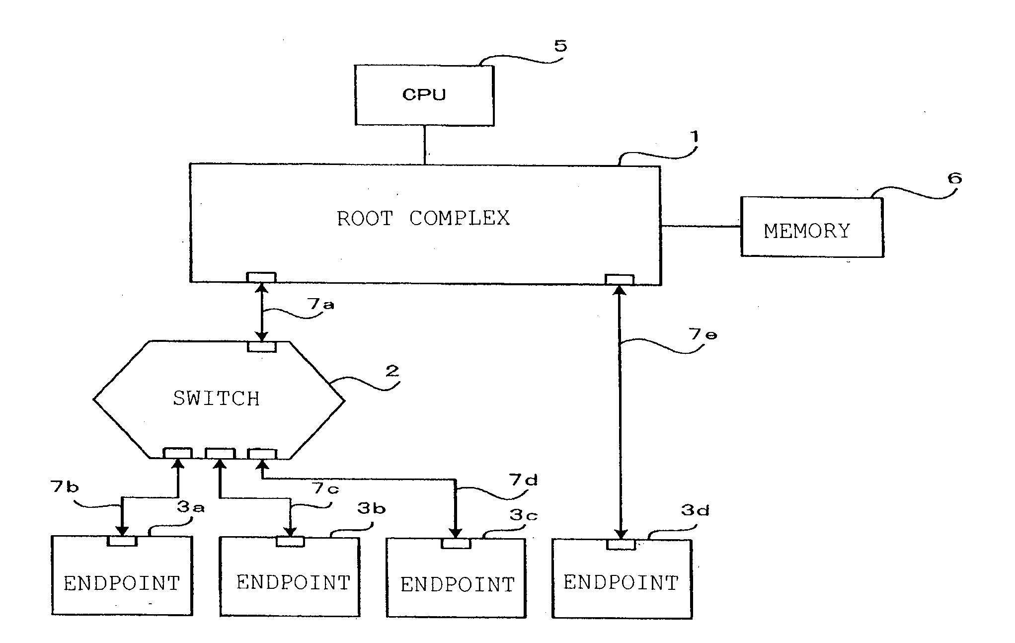
[0061]An embodiment of the present invention will now be described with reference to FIG. 4. FIG. 4 is a layout diagram of a TLP processing circuit of data transmitted in an upstream direction to the root complex 1 from endpoints 3a to 3c via a switch 2a constituting a relay device of a PCI Express system according to the present invention. The TLP processing circuit 10 in the downstream direction is the same in construction as that of FIG. 1, so a description thereof is omitted.

[0062]A switch 2a is provided between a root complex 1 and a plurality of endpoints 3a to 3c; the path of the root complex 1 and endpoint 3a (or 3b, 3c) is set beforehand by the PCI Express configuration software.

[0063]Also, on the link between the root complex 1 and the switch 2a and the link between the switch 2a and the endpoint 3a (or 3b, 3c), delivery confirmation and flow control are separately performed.

[0064]This flow control is not the subject of the gist of the present invention, so a description t...


PUM


Abstract

A PCI Express TLP processing circuit (10) comprises: a plurality of reception processing sections (2a1); a transmission processing section (2b); and a multiplexer (2c1) that performs transmission to the transmission processing section, selecting one of the reception processing sections; and at least a reception processing section comprises: a redundancy code generating circuit (12); an LCRC / sequential number detection circuit (13); a buffer memory (14); a packet control circuit section (16) that controls transmission for normal transmission to the transmission destination of the TLP in question or for nullifying transmission; and the transmission processing section comprises: a sequential number generating circuit (19); an LCRC generating circuit (20) and a relay circuit error detection circuit (21), whereby data integrity of the transmitted TLP can be guaranteed.

Description

CROSS-REFERENCE TO RELATED APPLICATION[0001]This application claims benefit of priority from Japanese application number JP2009-100756 filed Apr. 17, 2009; the entire contents of which are incorporated by reference herein.TECHNICAL FIELD[0002]The present invention relates to a PCI Express device and in particular to a processing circuit of transaction layer packets (TLP).BACKGROUND ART[0003]A PCI Express (registered trademark) bus is a high-speed serial interface employing point-to-point connection that has been developed in recent years for transferring data in computer systems and other electronic devices; the occupied area of the substrate of the bus is less than in the case of conventional parallel transfer, making possible further miniaturisation, and application of this technique in many fields is being studied.[0004]The details of the standard have been laid down as the PCI Express Base Specification by the PCI-SIG (Peripheral Component Interconnect-Special Interest Group), w...

Claims


Application Information

Patent Timeline
IPC IPC(8): G06F13/20
CPCH04L1/0045H04L2001/0097H04L1/0061G06F13/38G06F13/14H04L1/00H04L69/32
Inventor MURAKAMI, MASAYUKITAKEHARA, JUNARAMAKI, NARUHIKOKAWAMURA, TOSHIKAZUTAKAYANAGI, YOICHIOKABE, MOTOHIKO
Owner KK TOSHIBA
Learn More