
Magnet vibration device using external pressure and shoe having the same

a technology of magnet and vibration device, which is applied in the direction of magnets, vibration massage, vibration bodies, etc., can solve the problems of new vibration device, limited application, and inability to work normally, and achieve the effect of simple structure and little chance of breakdown

Inactive Publication Date: 2012-02-09
KIM SANG GU
View PDF2 Cites 5 Cited by
  • Summary
  • Abstract
  • Description
  • Claims
  • Application Information

AI Technical Summary

Benefits of technology

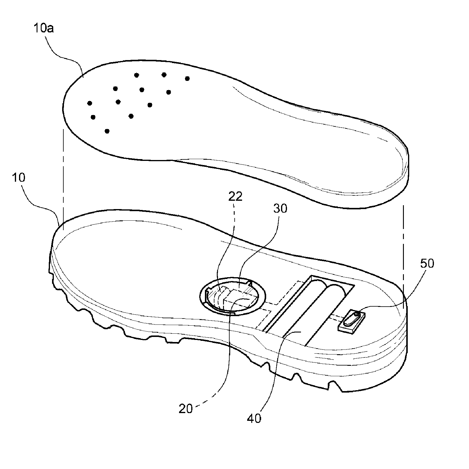
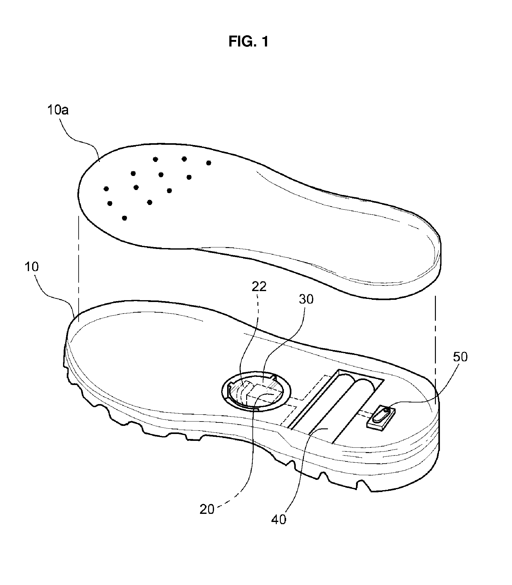
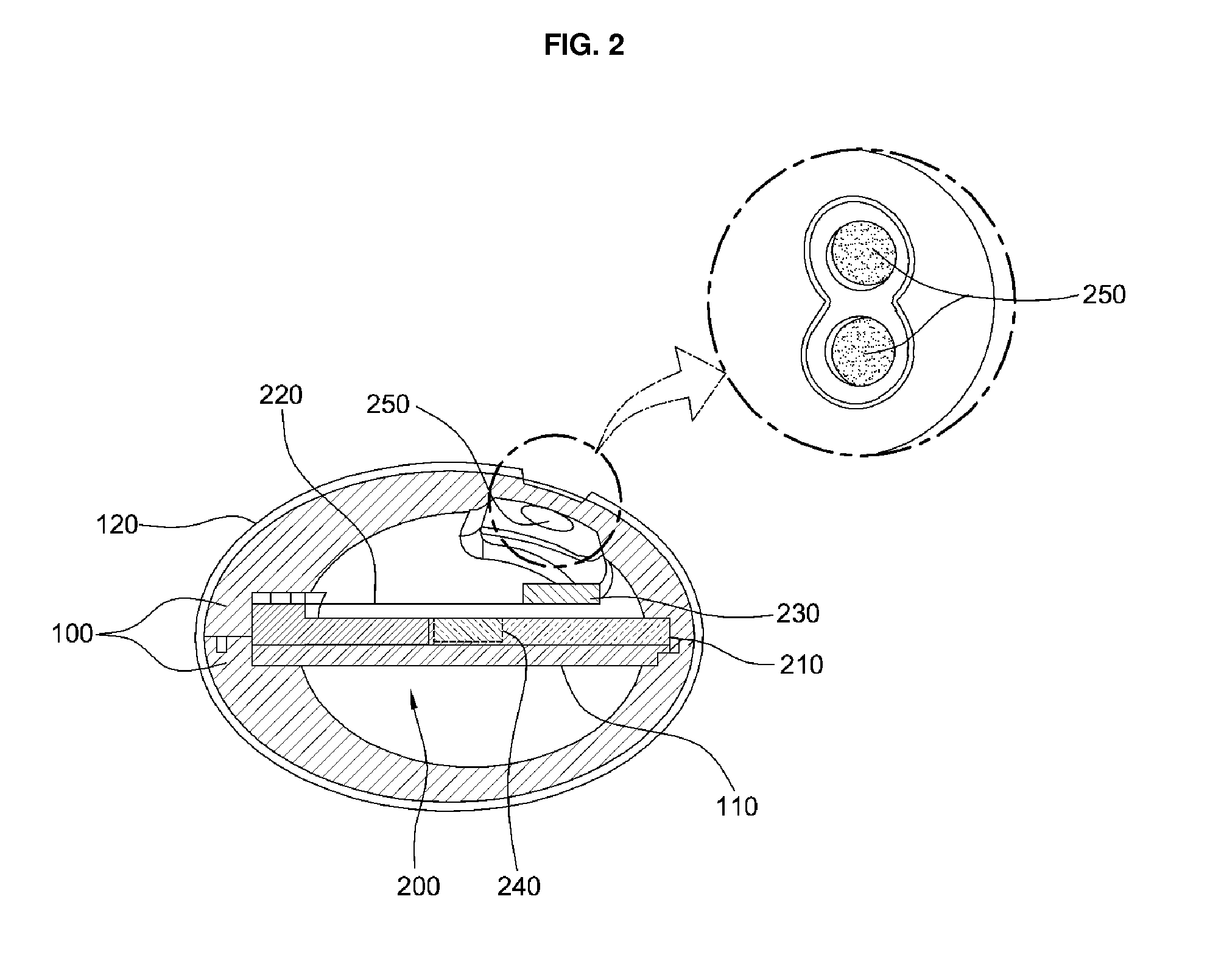
"The present invention provides a magnet vibration device that is simple, durable, and can be used in various fields. The device includes a case that changes shape when pressure is applied, a vibration plate inside the case, and two magnets (or three magnets) that generate a repulsive force when the vibration plate moves. The device can be embedded in a shoe to provide vibration to the wearer's body and improve blood flow. The device does not require additional energy sources and is compact and durable."

Problems solved by technology

However, such a shoe with the vibration function has several problems in that it requires a periodic exchange of the battery and in that it may not work normally due to a lot of breakdowns of the electric device.
Moreover, the conventional shoe with the vibration function has further problems in that it is complicated in structure, and in that it is restricted to be applied to other fields due to a problem of volume.
So, new vibration devices, which are simple in structure, have little chance for breakdowns, and are applicable to other fields, are in desperate need.

Method used


Image

  • Magnet vibration device using external pressure and shoe having the same
  • Magnet vibration device using external pressure and shoe having the same
  • Magnet vibration device using external pressure and shoe having the same

Examples


Embodiment Construction

[0032]Hereinafter, reference will be now made in detail to a magnet vibration device using external pressure according to the present invention with reference to the attached drawings.

[0033]The example embodiments described in this specification and the configurations illustrated in the drawings are just the most preferred embodiments of the present invention, and hence, they do not represent all technical ideas and scopes of the present invention. Accordingly, it should be understood that there is no intent to limit example embodiments of the invention to the particular forms disclosed, but on the contrary, example embodiments of the invention are to cover all modifications, equivalents, and alternatives falling within the scope of the invention.

[0034]FIG. 2 is a sectional view of a magnet vibration device using external force according to a first preferred embodiment of the present invention, FIG. 3 is an exploded perspective view of a vibration means according to the first prefer...


PUM

PropertyMeasurementUnit
external pressureaaaaaaaaaa
restoring forceaaaaaaaaaa
shapeaaaaaaaaaa

Abstract

Disclosed therein is a magnet vibration device, which is simple in structure, has little chance for breakdowns, and is applicable to various fields using vibration. The magnet vibration device includes: a case (100) that is changeable in shape by external pressure and has a restoring force when the shape of the case (100) is changed; a vibration plate (220) disposed inside the case (100) and changed in position in connection with the changed shape of the case (100); a first magnet (230) mounted on the vibration plate (220); and a second magnet (240) mounted at a position where a repulsive fore is generated between the first magnet (230) and the second magnet (240) when the position of the vibration plate (220) is changed.

Description

REFERENCE TO RELATED APPLICATIONS[0001]This is a continuation of pending International Patent Application PCT / KR2010 / 002914 filed on May 7, 2010, which designates the United States and claims priority of Korean Patent Application No. 10-2009-0040167, filed May 8, 2009 and Korean Patent Application No. 10-2009-0040170, filed May 8, 2009, the entire contents of which are incorporated herein by reference.FIELD OF THE INVENTION[0002]The present invention relates to a magnet vibration device using external pressure and a shoe having the same. More particularly, the present invention relates to a magnet vibration device using external pressure, which has a case with an elastic force and a restoring force and a vibration plate having a magnet and disposed inside the case in such a way as to generate vibration according to changes in the form of the case by external pressure.BACKGROUND OF THE INVENTION[0003]Recently, as an interest in functional shoes increases, various kinds of shoes with ...

Claims


Application Information

Patent Timeline
Patent Type & Authority Applications(United States)
IPC IPC(8): A43B13/14H01F7/02
CPCA43B1/0054A43B3/0005A61H2205/12A61H23/0218A61H39/04A43B7/146A43B3/34
Inventor KIM, SANG GU
Owner KIM SANG GU
Learn More