Thermal generator using magnetocaloric material
- Summary
- Abstract
- Description
- Claims
- Application Information
AI Technical Summary
Benefits of technology
Problems solved by technology
Method used
Image

Examples
first embodiment
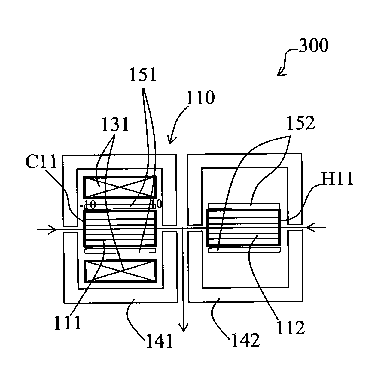
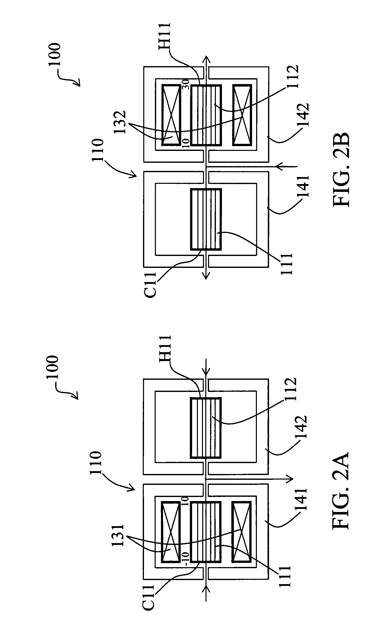
[0031]FIGS. 2A and 2B show, in schematic view, a thermal module 110 of a thermal generator 100 according to the present invention. This thermal module 110 comprises two magnetocaloric elements 111 and 112. The cold end C11 of the thermal module 110 is the end on the left side of FIGS. 2A and 2B of the first magnetocaloric element 111 and the hot end H11 of the thermal module 110 is the end on the right side of FIGS. 2A and 2B of the second magnetocaloric element 112. Each magnetocaloric element 111 and 112 is subjected to a magnetic cycle realized by one corresponding magnetic assembly 131, 132. During a first alternation (see FIG. 2A), the heat transfer fluid F flows from the cold end C11 of the magnetocaloric element 111 subjected to an increase of the magnetic field to the other end of this magnetocaloric element 111 (its hot end) and from the hot end H11 of the magnetocaloric element 112 subjected to a decrease of the magnetic field to the other end of this magnetocaloric elemen...
second embodiment
[0034]FIGS. 3A and 3B show, in schematic view, a thermal module 210 of a thermal generator 200 according to the present invention. This example is particularly adapted for rotational thermal generators 200 where the magnetic assemblies 231, 232, 233 are fixed to a shaft in rotation around the longitudinal axis 5 of the generator 200. FIGS. 4A and 4B represent a simplified front view of this thermal generator 200 showing more particularly one part of a magnetic assembly 231 in the positions corresponding respectively to these of FIGS. 3A and 3B.
[0035]These FIGS. 4A and 4B show the interaction between the magnetic assemblies 231 and one magnetocaloric element 211, 1211, 2211, 3211, 4211, 5211, 6211 and 7211 of the eight thermal modules 210, 1210, 2210, 3210, 4210, 5210, 6210 and 7210 of this thermal generator 200. Each magnetic assembly 231, 232, 233 is constituted by two groups of four permanent magnets facing each other and forming a magnetic gap 6 in which the magnetocaloric materi...
PUM
 Abstract
Description
Claims
Application Information
 - Generate Ideas
- Intellectual Property
- Life Sciences
- Materials
- Tech Scout
- Unparalleled Data Quality
- Higher Quality Content
- 60% Fewer Hallucinations
Browse by: Latest US Patents, China's latest patents, Technical Efficacy Thesaurus, Application Domain, Technology Topic, Popular Technical Reports.
© 2025 PatSnap. All rights reserved.Legal|Privacy policy|Modern Slavery Act Transparency Statement|Sitemap|About US| Contact US: help@patsnap.com