Kitchen appliance

a technology for kitchen appliances and support surfaces, applied in the field of kitchen appliances, can solve the problems of not being able to meet the needs of many users, still be able to be considered troublesome by some users to manually rotate the tube, and still be able to reach the support surface with food drops, so as to achieve good pouring performance, reduce the risk of food drops on the support surface, and simple and robust design of the spou

Inactive Publication Date: 2012-02-09
KONINKLIJKE PHILIPS ELECTRONICS NV
View PDF73 Cites 3 Cited by
  • Summary
  • Abstract
  • Description
  • Claims
  • Application Information

AI Technical Summary

Benefits of technology

[0012]Furthermore, this provides that the movement of the spout is effected by the pouring spout of the jug. Consequently, the user does not have to actuate or manipulate the spout him- or herself. Instead displacement of the jug will bring the pouring spout into contact with the spout of the kitchen appliance and will toggle its movement. As the spout of the kitchen appliance is partially inserted into the pouring spout, the risk of dripping on the support surface is even further reduced. By providing that the spout of kitchen appliance is moved by the pouring spout of the jug an automatic movement is achieved eliminating any conscious action with respect to the movement of the spout to be taken by the user.
[0013]In an embodiment said manipulator comprises an upper guide surface of the pouring spout of the jug, which upper guide surface is arranged to contact the spout of the kitchen appliance and is arranged to urge it into said first position when the spout of the kitchen appliance is inserted, at least partially, into the pouring spout of the jug. This provides again that the movement of the spout is effected by the pouring spout of the jug, the user does not have to actuate or manipulate the spout him- or herself. Instead placement of the jug in a position in which is ready to receive foodstuff from the kitchen appliance will bring the pouring spout into contact with the spout of the kitchen appliance and will toggle its movement towards its first position automatically.
[0014]In an embodiment the spout of the kitchen appliance is angled downward with respect to the horizontal axis between 5 and 25 degrees, preferably about 15 degrees, in said first position, and is angled upward with respect to the horizontal axis between 3 and 15 degrees, preferably about 5 degrees, in said second position. These angles provide good pouring performance of the spout of the kitchen appliance and assure that no drops will reach the support surface as the spout will be angled upward sufficiently in its second position.
[0015]In an embodiment the spout of the kitchen appliance comprises a first distal which extends, at least partly, into the housing and is arranged to receive pourable foodstuff from the outlet, and comprises an open distal end which protrudes from the housing. This provides a simple and robust design of the spout which can be easily manipulated between its two positions.

Problems solved by technology

This is considered troublesome for many users.
Although the solution of WO 2009 / 010897 provides a solution to the above-mentioned concern, it may still be considered troublesome by some users to rotate the tube manually, which requires some substantial rotation, i.e. over 180 degrees.
In case the jug is removed prior to rotation of the spout, there is still a considerable risk of drops of foodstuff reaching the support surface.

Method used


Image

  • Kitchen appliance
  • Kitchen appliance
  • Kitchen appliance

Examples


Embodiment Construction

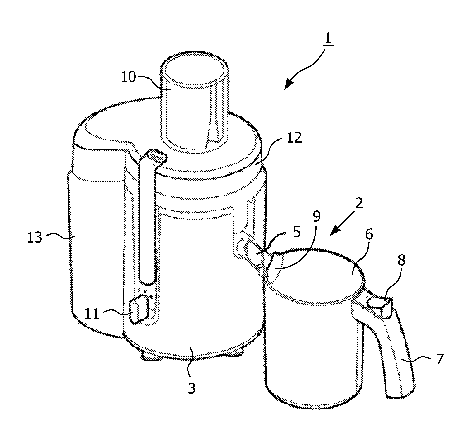
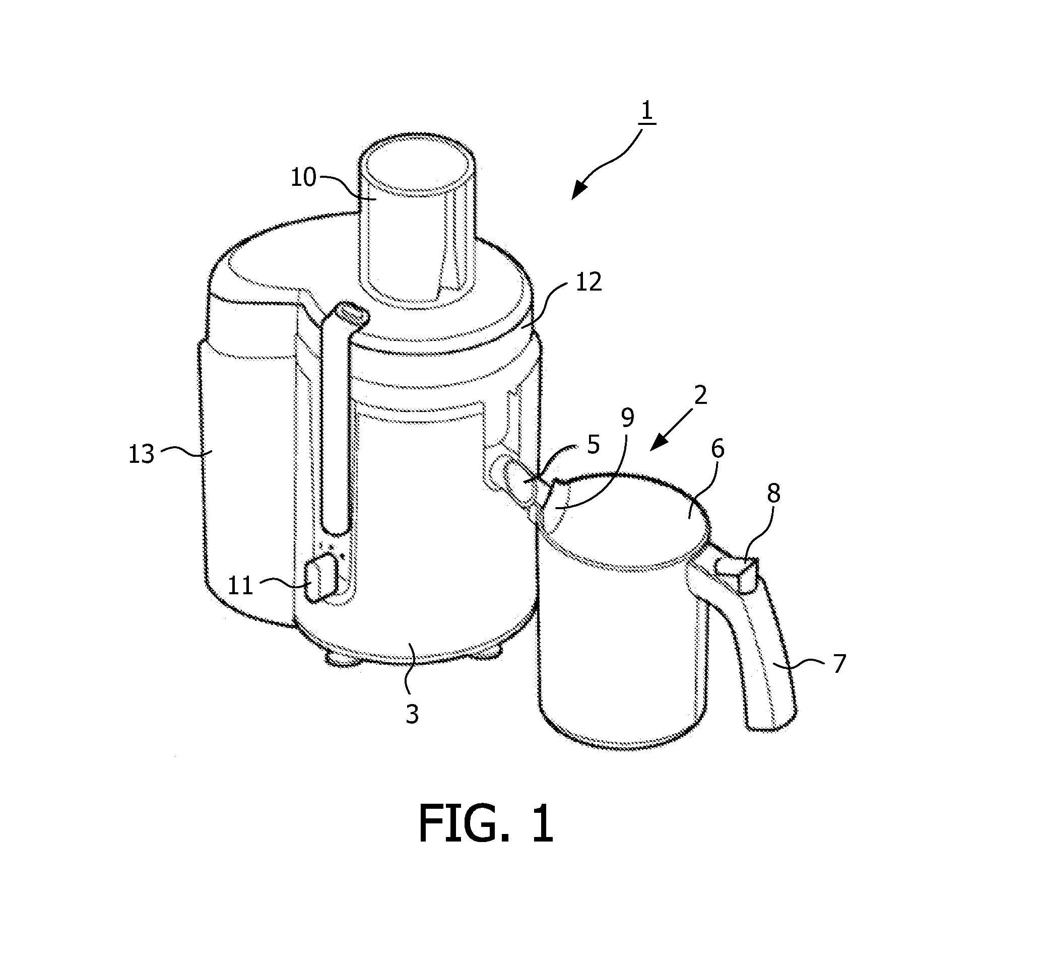
[0032]In the below description of the invention the kitchen appliance incorporating the invention will be described in the example of a juice extractor. It is emphasized here that the invention is not limited nor intended to be limited to such a juice extractor, but is equally applicable to other kitchen appliances such as blenders, mixers and the like and even to coffee making machines and general purpose water dispensers for example. In other words, the invention is applicable to kitchen appliances that are arranged to process foodstuff and can supply pourable foodstuff, such a juice from fruit and / or vegetables, milkshakes etcetera. In other words, foodstuff that has a certain amount of liquidity.

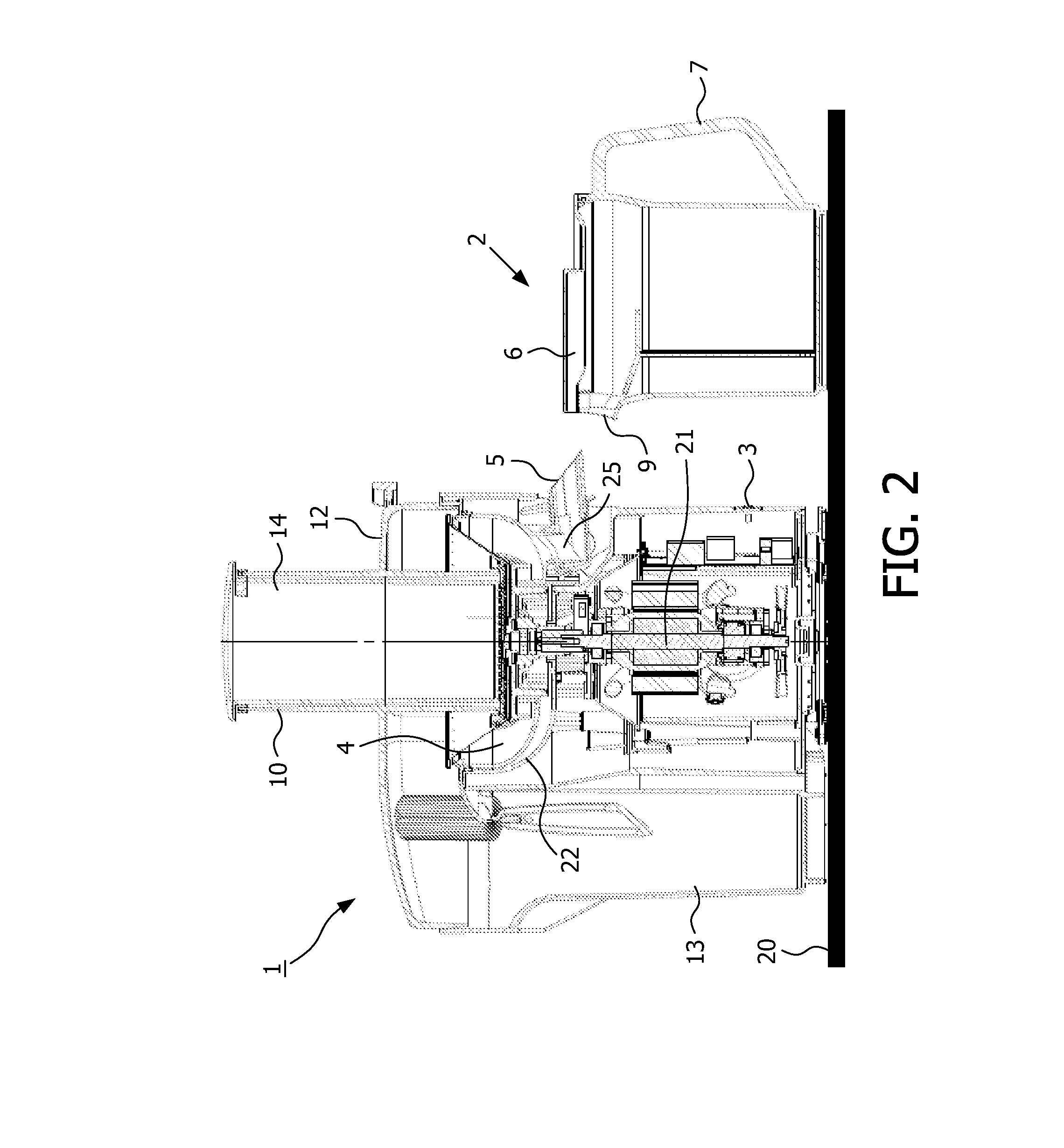
[0033]FIG. 1 shows a kitchen appliance 1, which as indicated is in the example of a juice extractor together with a jug or juice jug 2. The juice extractor 1 comprises a housing 3 which surrounds a cavity 4 (see FIG. 2). The juice extractor 1 is further provided with a spout 5, which is ...


PUM


Abstract

A kitchen appliance (1) for processing foodstuff comprises housing (3) surrounding a cavity (4) for receiving said foodstuff The appliance further comprises an outlet (25) for dispensing pourable foodstuff from the housing (3) and a collector (22) to receive and collect pourable foodstuff and delivering the pourable foodstuff to the outlet (25). The outlet (25) has a spout (5), said spout (5) being hingeable about a substantially horizontal axis (23) between a first position in which the pourable foodstuff can be dispensed from the spout (5) and a second position in which dispensing of the pourable foodstuff from the spout (5) is prevented. Said spout (5) is constructed and arranged to be manipulated by a manipulator acting on the spout (5) so as to urge the spout (5) towards the second position.

Description

FIELD OF THE INVENTION[0001]The present invention relates to a kitchen appliance, a jug designed to co-operate with a kitchen appliance and an assembly of a kitchen appliance and a jug. In particular the invention relates to a kitchen appliance known as a juice extractor which is provided with means to prevent drops of juice to reach a support surface of the kitchen appliance.BACKGROUND OF THE INVENTION[0002]Kitchen appliances which are used to process foodstuff can be found in many kitchens of both families, restaurants etcetera. A particular type of kitchen appliance used in processing foodstuff is designed to process foodstuff such, that a pourable or liquidized foodstuff is obtained. Such kitchen appliances are for example mixers, blenders and juice extractors. Such devices are widely known and are for example used to extract the juice present in fruit or vegetables, or to blend certain foodstuffs so that people may enjoy the consummation of such foodstuff including all the good...

Claims


Application Information

Patent Timeline
Patent Type & Authority Applications(United States)
IPC IPC(8): B02C25/00
CPCA47J19/027
Inventor PUCHER, HERFRIED
Owner KONINKLIJKE PHILIPS ELECTRONICS NV
Why Eureka
Try Eureka