Head-protecting airbag apparatus

a technology for airbags and head protection, which is applied in the direction of pedestrian/occupant safety arrangements, vehicular safety arrangments, vehicle components, etc., can solve the problems of delay in the inflation of the supporting inflatable region relative, and achieve the effect of improving the material yield of the airbag

Active Publication Date: 2012-02-09
TOYODA GOSEI CO LTD
View PDF6 Cites 8 Cited by
  • Summary
  • Abstract
  • Description
  • Claims
  • Application Information

AI Technical Summary

Benefits of technology

[0018]This configuration will help prevent an inflation gas from flowing into the communication channel in an initial stage of inflation of the shielding section as much as possible since the communication channel is located above the gas feed channel in a flattened state, thereby delaying an initiation of inflation of the supporting inflatable region relative to the shielding section in a steady fashion.
[0019]In the airbag apparatus described above, it is desired that the shielding section includes, in an area thereof overlapping with the supporting inflatable region, a communicating area that makes the gas feed channel communicate with the protection region in a vertical direction. With this configuration, the area of the shielding section overlapping with the supporting inflatable region, i.e., the area supported by the supporting inflatable region at full inflation of the supporting inflatable region, will inflate in a single plate shape extending in a vertical direction. That is, the area is not likely to bend in an inboard or outboard direction, thereby stabilizing a moving amount of the lower end of the shielding section toward an interior of a vehicle (or a slanting amount of the shielding section) when the supporting inflatable region supports the shielding section, and assuring an arrest of an occupant.
[0020]Moreover, if the above airbag apparatus is provided with means for preventing the supporting inflatable region from slipping upward at airbag deployment, the supporting inflatable region will be steadily positioned between the vicinity of the upper end of the shielding section and the member of the vehicle body structure at airbag deployment.
[0021]To this end, it is desired that the supporting inflatable region is so elongate in a front and rear direction as to stride over at least one of mounting portions that are arranged along a front and rear direction on the upper edge of the shielding section for mounting the upper edge of the shielding section on the member of the vehicle body structure. With this configuration, the mounting portion is secured to the member of the vehicle body structure above the supporting inflatable region, and therefore will prevent the supporting inflatable region from slipping upward from the shielding section and / or prevent the supporting inflatable region from being located on an inboard side of the shielding section.
[0022]Furthermore, it is desired that the communication channel narrows toward the supporting inflatable region and the turn-round region is located in an intermediate position in a length direction of the communication channel. With this configuration, an inflation gas will pool in a wider area of the communication channel located on the side of the shielding section relative to the turn-round region until the gas flows into the supporting inflatable region, and once an inner pressure rises the gas will separate the panels defining the turn-round region and flow into the supporting inflatable region without delay, in spite of the constricted outlet to the supporting inflatable region. As a result, the timing of inflow of an inflation gas into the supporting inflatable region will be further stabilized.
[0023]It will also be appreciated to prepare the supporting inflatable region separate from the shielding section. This configuration will reduce remaining materials which would be formed around the supporting inflatable region due to partial protrusion of the supporting inflatable region and discarded in comparison with an instance where the supporting inflatable region was integral with the shielding section, and therefore, will improve a material yield of the airbag.

Problems solved by technology

The airbag includes an inflatable shielding section that is adapted to be secured to a member of a vehicle body structure by an upper edge thereof in the upper edge of the window and covers the window at full airbag deployment, a supporting inflatable region that is in gas communication with the shielding section and deployable between an outboard side of a vicinity of an upper end of the shielding section and the member of the vehicle body structure in at least an upper area of the window, and delaying means that delays inflation of the supporting inflatable region relative to the shielding section.

Method used


Image

  • Head-protecting airbag apparatus
  • Head-protecting airbag apparatus
  • Head-protecting airbag apparatus

Examples


Embodiment Construction

[0036]Preferred embodiments of the present invention are described below with reference to the accompanying drawings. However, the invention is not limited to the embodiments disclosed herein. All modifications within the appended claims and equivalents relative thereto are intended to be encompassed in the scope of the claims.

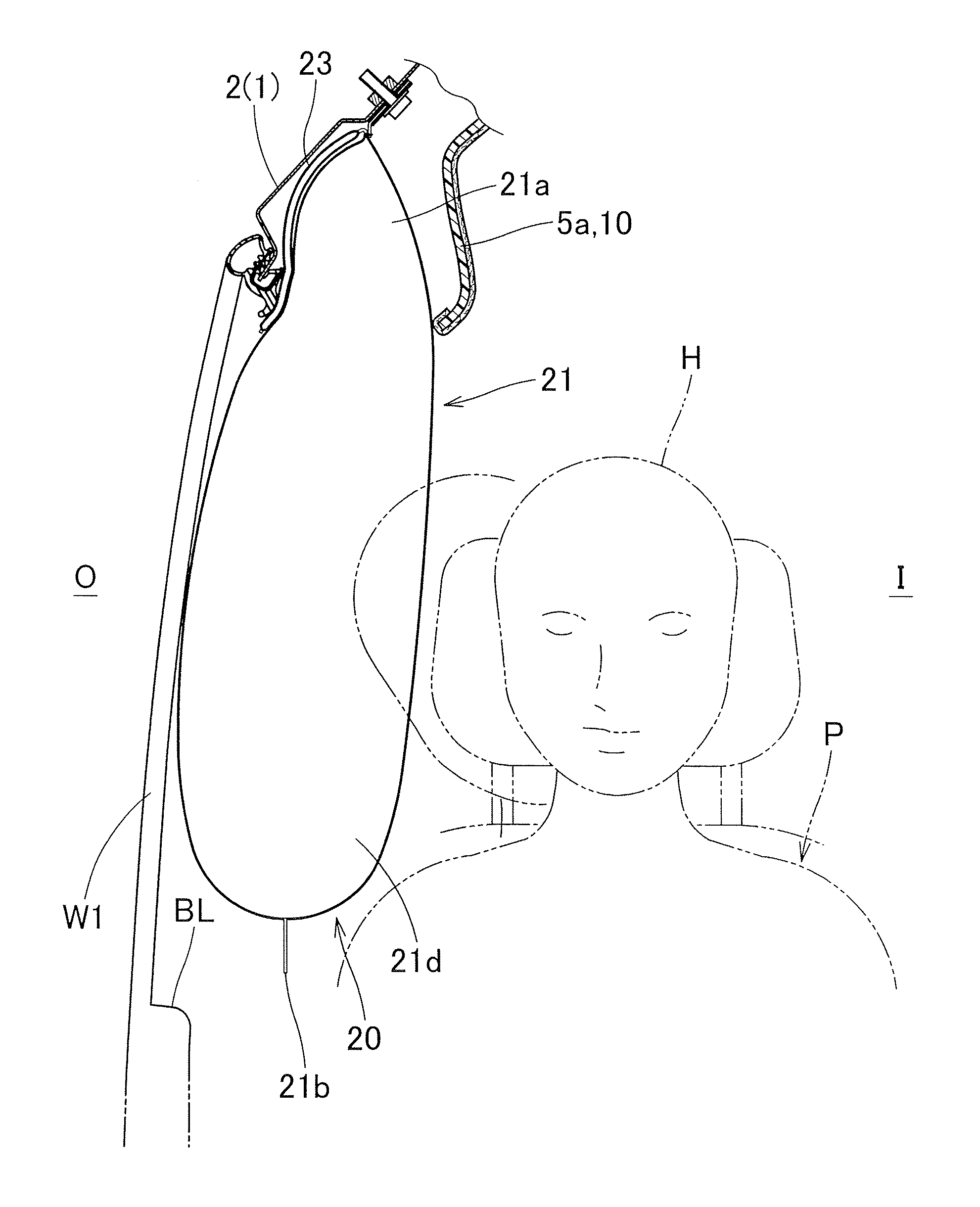
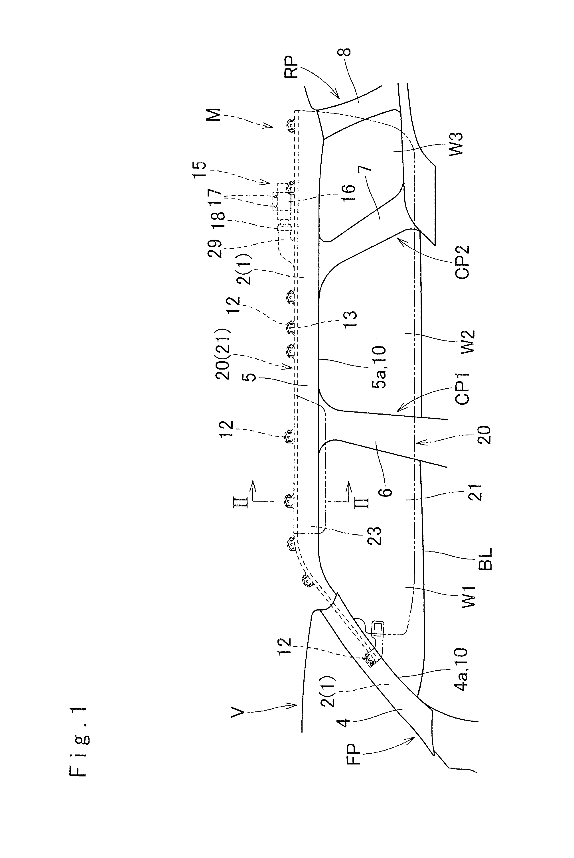
[0037]As shown in FIG. 1, an airbag apparatus M embodying the present invention is mounted on a vehicle V with three side windows W1, W2 and W3 and corresponding three rows of seats. The airbag apparatus M includes an airbag 20, an inflator 15, a mounting bracket 16, a plurality of mounting brackets 12 and an airbag cover 10. The airbag 20 is housed on upper peripheries of the side windows W1, W2 and W3 in an folded-up configuration, specifically from the lower periphery of a front pillar FP through the region above a rear pillar RP, along the lower periphery of a roof side rail RR, on an inboard side of the vehicle V.

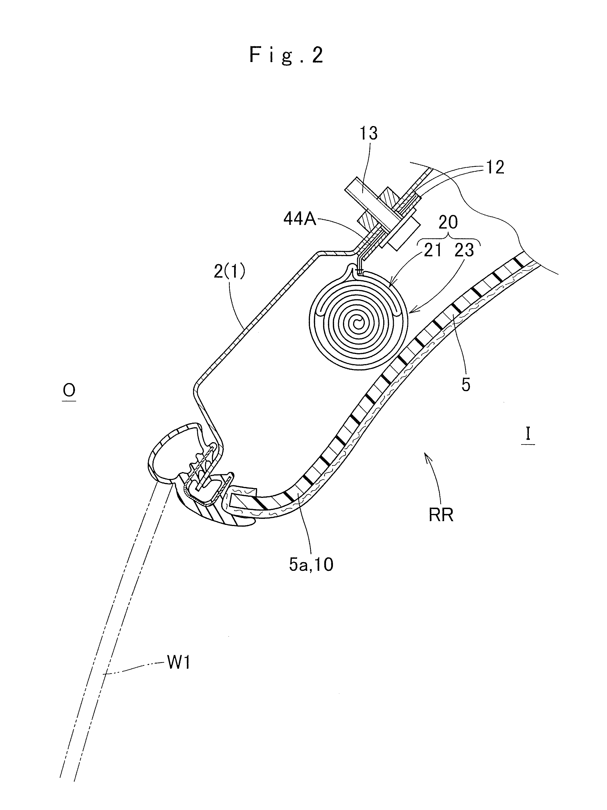
[0038]As shown in FIGS. 1 and 2, the airba...


PUM


Abstract

A head-protecting airbag apparatus mountable on a vehicle having a window is disclosed. The airbag apparatus includes an airbag adapted to be secured to a member of a vehicle body structure by an upper edge thereof in an upper edge of the window and housed in the upper edge of the window in a folded-up configuration. The airbag includes an inflatable shielding section that covers an inboard side of the window at full airbag deployment, a supporting inflatable region that is in gas communication with the shielding section and deployable between an outboard side of a vicinity of an upper end of the shielding section and the member of the vehicle body structure in an upper area of the window, and delaying means that delays inflation of the supporting inflatable region relative to the shielding section. The supporting inflatable region inflates after the shielding section does between the shielding section and the member of the vehicle body structure, and supports the outboard side of the vicinity of the upper end of the shielding section.

Description

CROSS REFERENCE TO RELATED APPLICATIONS[0001]The Present application claims priority from Japanese Patent Application No. 2010-176435 of Tanaka et al., filed on Aug. 5, 2010, the disclosure of which is hereby incorporated into the present application by reference.BACKGROUND OF THE INVENTION[0002]1. Field of the Invention[0003]The present invention relates to a head-protecting airbag apparatus including an airbag that is mountable on an upper periphery of a vehicle window in a folded-up configuration and deployable downward for covering an inboard side of the window when fed with an inflation gas.[0004]2. Description of Related Art[0005]JP2010-36805 discloses a head-protecting airbag apparatus including an airbag that is provided with a shielding section for covering an inboard side of a window in order to hold a vehicle occupant inboard and protect him / her during a rollover event of a vehicle possibly occurring after a side impact. The shielding section includes an extended lower en...

Claims


Application Information

Patent Timeline
Patent Type & Authority Applications(United States)
IPC IPC(8): B60R21/16
CPCB60R21/213B60R21/2334B60R21/232
Inventor TANAKA, MOTOYUKISATO, JUNMIZUNO, YUSHIOOCHIAI, YASUO
Owner TOYODA GOSEI CO LTD
Why Eureka
Try Eureka