Threaded joint for tubes, pipes and the like

a technology for threaded joints and pipes, applied in the direction of threaded joints, fluid pressure sealed joints, joints with sealing surfaces, etc., can solve the problems of plastic deformation of metal parts in the joint portions, high torque required during make-up operations, and the increase of hardware and devices for hydrocarbons. the effect of increasing the sealability of the join

Inactive Publication Date: 2012-02-09
TENARIS CONNECTIONS
View PDF3 Cites 28 Cited by
  • Summary
  • Abstract
  • Description
  • Claims
  • Application Information

AI Technical Summary

Benefits of technology

[0037]Moreover, if the joint is provided with metal-to-metal seals, i.e. in the case in which the slant shaped surfaces of the pin ends are made in two steps, said last rotation of the coupling guarantees the shoulder contact and energizes the seal, increasing the sealability of the joint.

Problems solved by technology

Searching for oil or, more generally, hydrocarbons has become more demanding in terms of hardware and devices in recent years because oil and gas fields or reservoirs are located deeper under the earth's surface or in places difficult to reach.
However designing joints having good resistance to high loads generally means that high torques are required during make-up operations, at least in the last part of the make-up operation, just before the abutment shoulder is energized with danger of plastic deformation of the metal in the joint portions.
In this part of the make-up there is also the danger of causing galling between sealing surfaces.
Both solutions cited above are unsatisfactory because some problems remain unsolved.
A first problem is handling fragility due to the castellated pin ends and inner seal support.
In fact if a lug or a groove of a castellated pin end is hit and bent during the handling of the pipe in the yard, the make-up will be much more difficult, with the risk of cross threading and galling increasing dramatically.
It may also harm the internal flush or drift.
Another problem relates to manufacturing, because the lugs and grooves, as well as the inner seal support, have to be machined with very precise tolerances, increasing the cost of the connection and the time needed to machine it.
Moreover it is technically complicated to cut a right handed thread and a left handed thread at the same time.
It is impractical from the cost aspect.
Still another problem is encountered during joint make-up in both solutions of the state of the art.
First of all there is a danger of galling the seal surfaces, and plastic deformation of the pin noses, seal surfaces or shoulder surfaces during make-up of the connection.

Method used


Image

  • Threaded joint for tubes, pipes and the like
  • Threaded joint for tubes, pipes and the like
  • Threaded joint for tubes, pipes and the like

Examples


Embodiment Construction

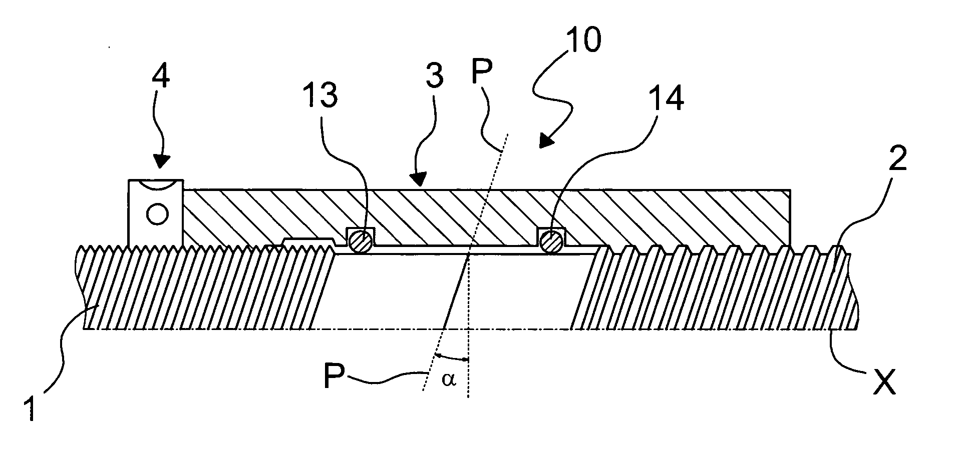
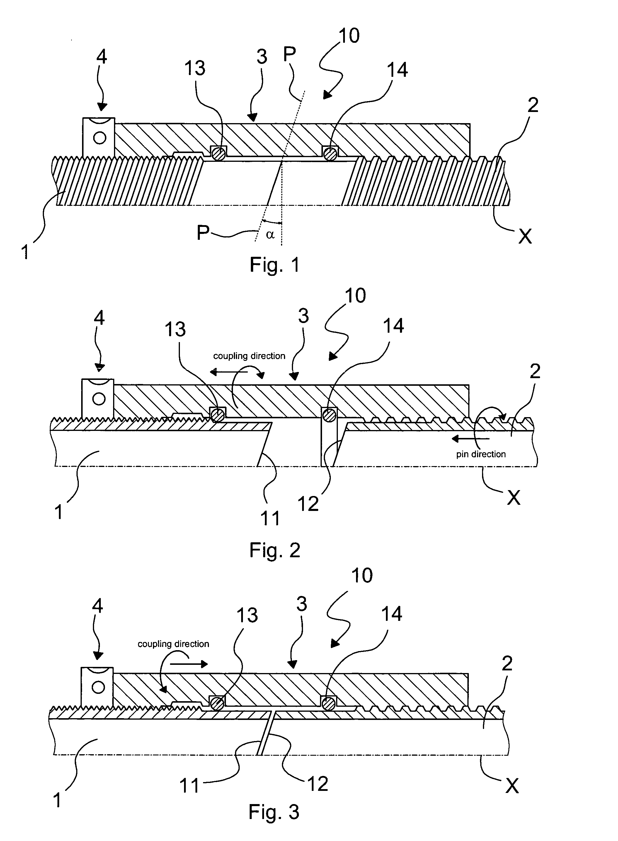
[0053]With particular reference to the figures, the joint of the invention, indicated globally with reference numeral 10, comprises a first pin 1 having a larger pitch thread and a second pin 2 having a smaller pitch thread, and a mating coupling 3 forming the coupling of the joint. In a first embodiment of the joint, shown in a made up position in FIG. 1, slanted shaped ends of both pins are in mutual contact. A back nut 4 can be advantageously used to prevent the connection from opening due to over-torques. More precisely, the combination of the effects of the slanted shaped pin ends and the use of the back nut 4 provides a joint that can support extremely high torques.

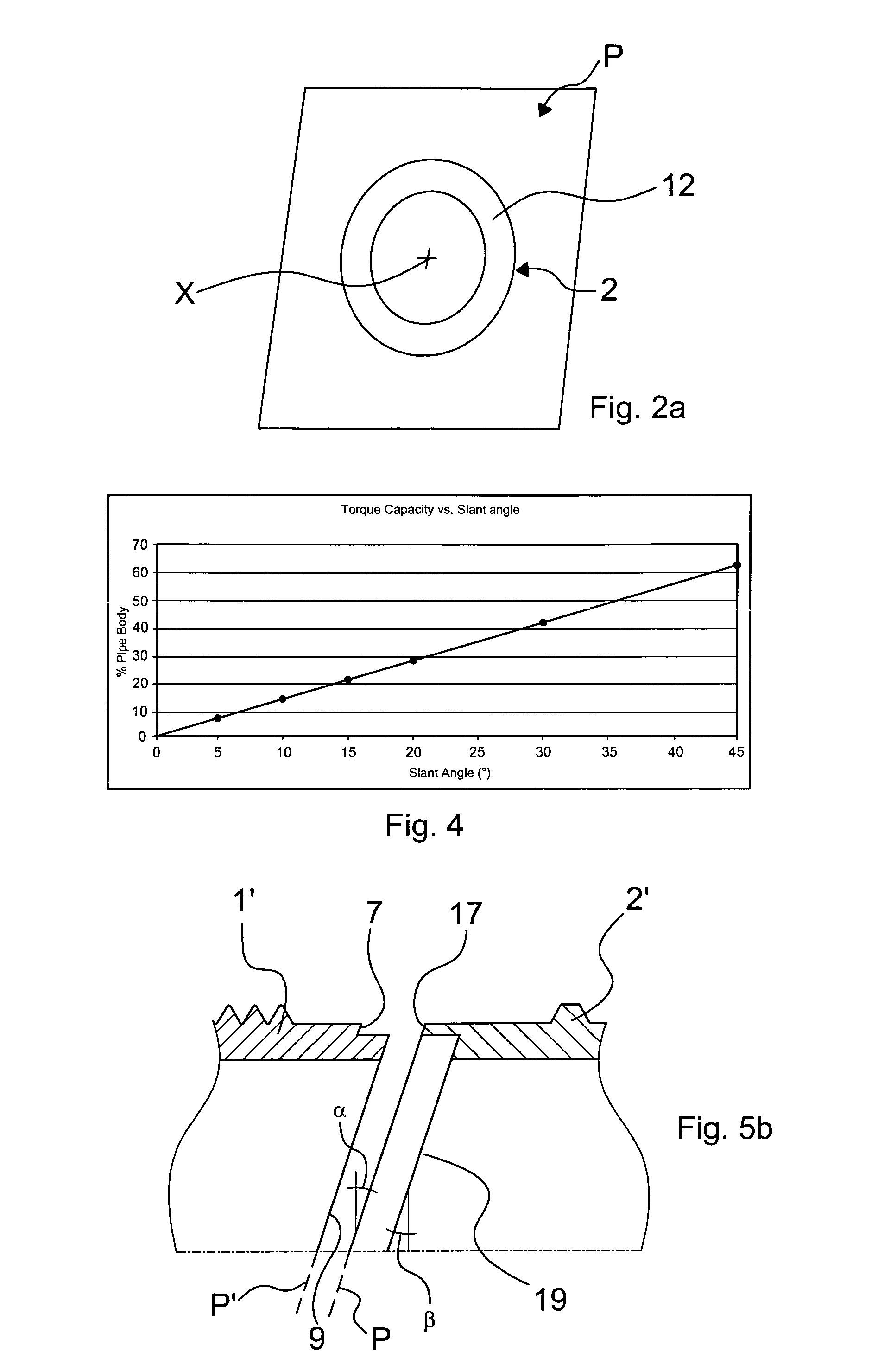
[0054]Although the joint 10 can have the threaded portions of both pins 1 and 2 cylindrical, better performances are obtained when at least one pin, e.g. pin 2, is tapered in the threaded portion, with a taper angle to the joint axis X of at least a few degrees, corresponding to an inclination comprised between 6.25...


PUM


Abstract

A threaded joint comprises a coupling, a first pin, and a second pin, wherein the thread of the first pin has a pitch different from the pitch of the thread of the second pin. The extremities of the pins have slanted contact surfaces of complementary shape that make mutual contact after make-up of the joint. The slanted common plane of contact of both pins has an angle to the plane perpendicular to the longitudinal axis of the joint which is greater than 0°. In an alternative embodiment the contact surfaces of the pins are split into two staggered planes and comprise a seal in-between.

Description

FIELD OF THE INVENTION[0001]The present invention relates to a threaded joint or connection for tubes, pipes and the like, in particular for connecting tubes of predefined length to make strings used in the hydrocarbon industry, especially for use in the field of OCTG (Oil Country Tubular Goods), for use in drilling especially in applications where it is preferable that said pipes do not rotate during make-up operations, and in line pipes.BACKGROUND OF THE INVENTION[0002]Searching for oil or, more generally, hydrocarbons has become more demanding in terms of hardware and devices in recent years because oil and gas fields or reservoirs are located deeper under the earth's surface or in places difficult to reach. Prospecting for and exploitation of hydrocarbon fields demands hardware which can withstand higher loads and ensures optimal sealability. The market for so-called premium connections is increasing and research is being carried out to offer new improved joints to meet market n...

Claims


Application Information

Patent Timeline
Patent Type & Authority Applications(United States)
IPC IPC(8): F16L15/04F16L17/02F16L15/00
CPCE21B17/0423E21B17/0426F16L15/003F16L15/04F16L15/008F16L15/009F16L15/004
Inventor CARCAGNO, GABRIEL E.QUIROGA, ALFREDO FRANCISCO
Owner TENARIS CONNECTIONS
Why Eureka
Try Eureka