Linear variable differential transformers

a transformer and variable technology, applied in the field of transformers, can solve the problems of increasing the maintenance cost of the engine, increasing the risk of corrosion, and frequent replacemen

Active Publication Date: 2012-02-09
HONEYWELL INT INC
View PDF4 Cites 14 Cited by
  • Summary
  • Abstract
  • Description
  • Claims
  • Application Information

AI Technical Summary

Problems solved by technology

For example, in some engines, the linear variable differential transformer components are exposed to a harsh environment in front or around the engine and may be more susceptible to corrosion.
The high-temperature environment may decrease the winding and termination reliability of the linear variable differential transformers causing frequent need for replacement and increase in maintenance costs of the engine.
In addition high temperature introduces measurement error that must be accounted for through component design and / or signal conditioning.

Method used


Image

  • Linear variable differential transformers
  • Linear variable differential transformers
  • Linear variable differential transformers

Examples


Embodiment Construction

[0016]The following detailed description is merely exemplary in nature and is not intended to limit the inventive subject matter or the application and uses of the inventive subject matter. Furthermore, there is no intention to be bound by any theory presented in the preceding background or the following detailed description.

[0017]An improved linear variable differential transformer has been provided that can be employed in a wide range of temperature environments, such as in temperatures of between about −60° C. to about 500° C. The linear variable differential transformer includes a core comprising two different materials, where one material is a magnetic material and the other material is a non-magnetic material.

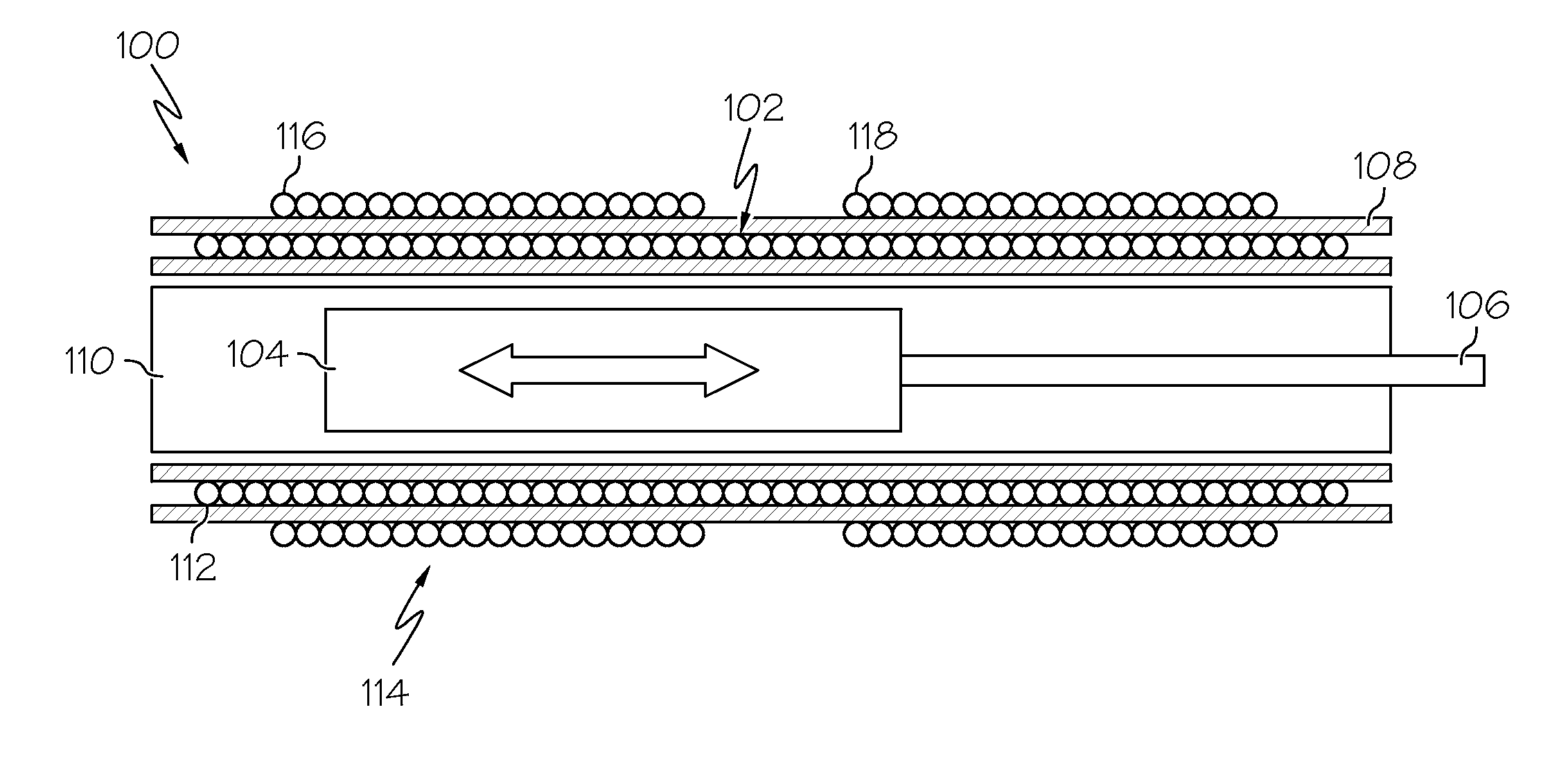
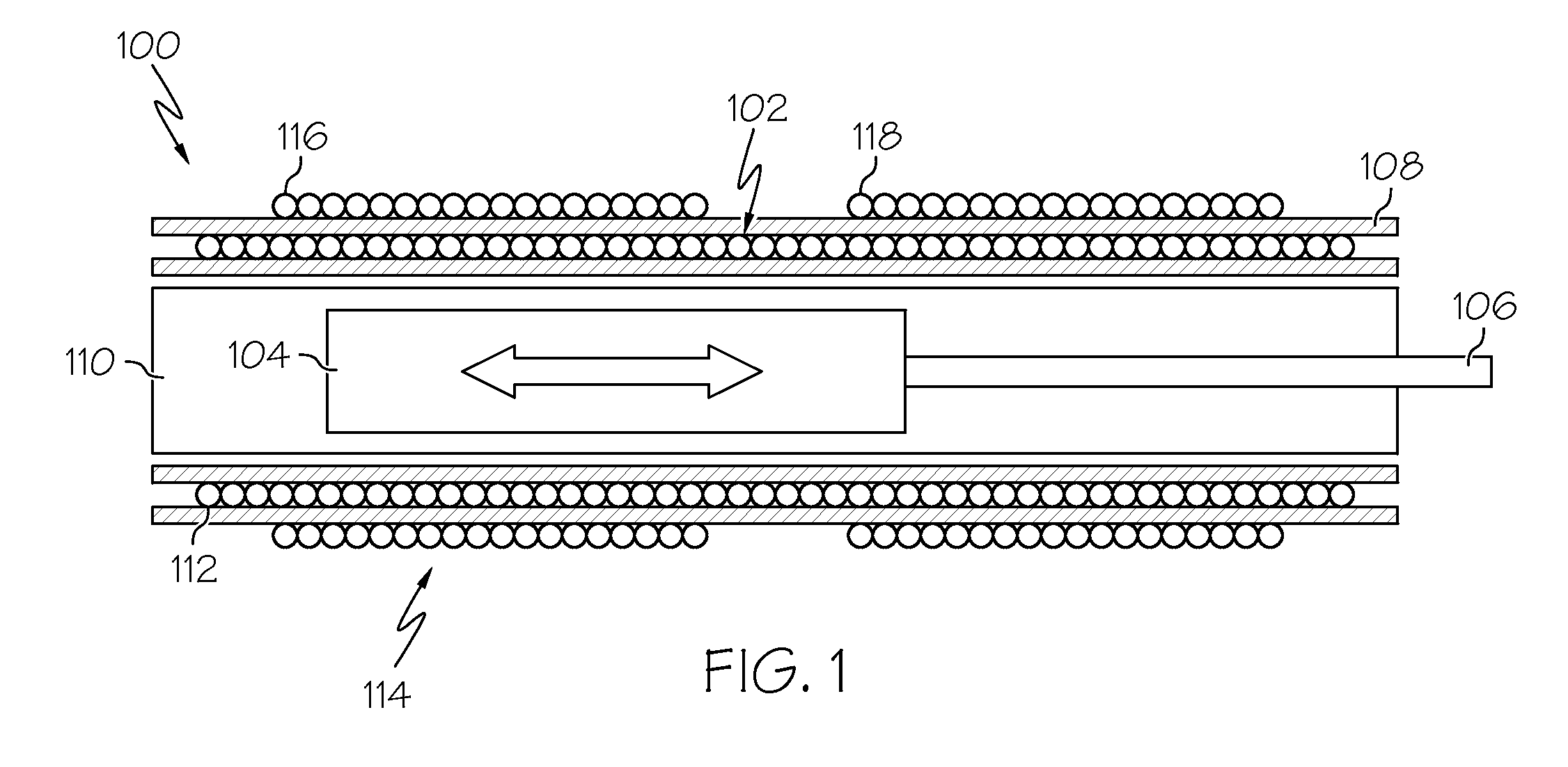
[0018]FIG. 1 is a cross-sectional view of a simplified linear variable differential transformer (LVDT) 100, according to an embodiment. The LVDT 100 includes a coil assembly 102 and a core 104 affixed to a rod 106. The coil assembly 102 is disposed in a housing 108 and in...


PUM

PropertyMeasurementUnit
temperaturesaaaaaaaaaa
radial cross-sectional areaaaaaaaaaaa

Abstract

Linear variable differential transformers include a core comprising a non-ferromagnetic material and a ferromagnetic material, and a coil assembly including an axial bore within which the core is disposed and through which the core axially translates.

Description

TECHNICAL FIELD[0001]The inventive subject matter generally relates to transformers, and more particularly relates to linear variable differential transformers.BACKGROUND[0002]Gas turbine engines typically have fuel supply systems for delivering fuel to a combustor, where the fuel is ignited to produce a thrust. In many engines, the fuel is stored in a fuel source, such as a fuel tank, and is drawn out by one or more pumps. The pumps pressurize the fuel and deliver the pressurized fuel to manifolds in the combustor via a main supply line. To control the rate at which the fuel flows through the system, the main supply line may include one or more valves in flow series between the pumps and the fuel manifolds. These valves generally include at least a main metering valve and a bypass valve. The bypass valve may be disposed in a bypass flow line connected upstream of the metering valve for allowing a portion of the fuel flowing in the main supply line back to the inlet of the one or mo...

Claims


Application Information

Patent Timeline
Patent Type & Authority Applications(United States)
IPC IPC(8): H01F27/28H01F17/04H01F27/255
CPCG01D5/2291H01F2003/106H01F21/06
Inventor FOX, RICHARDHOLDEN, GENEFRANCONI, ROBERT
Owner HONEYWELL INT INC
Why Eureka
Try Eureka