
Scanned Image Projection System Employing Beam Folding Apparatus

a beam folding and projection system technology, applied in the direction of instruments, static indicating devices, optical elements, etc., can solve the problems of limiting the mobility of the presenter, consuming small amount of power, and yet delivering bright images

Inactive Publication Date: 2012-02-09
MICROVISION
View PDF2 Cites 55 Cited by
  • Summary
  • Abstract
  • Description
  • Claims
  • Application Information

AI Technical Summary

Problems solved by technology

These systems consume small amounts of power yet deliver bright, complex images.
This results in the presenter generally having his back facing the audience, which is less than desirable.
This “hard wire” restriction limits the mobility of the presenter while making a presentation.

Method used


Image

  • Scanned Image Projection System Employing Beam Folding Apparatus
  • Scanned Image Projection System Employing Beam Folding Apparatus
  • Scanned Image Projection System Employing Beam Folding Apparatus

Examples


Embodiment Construction

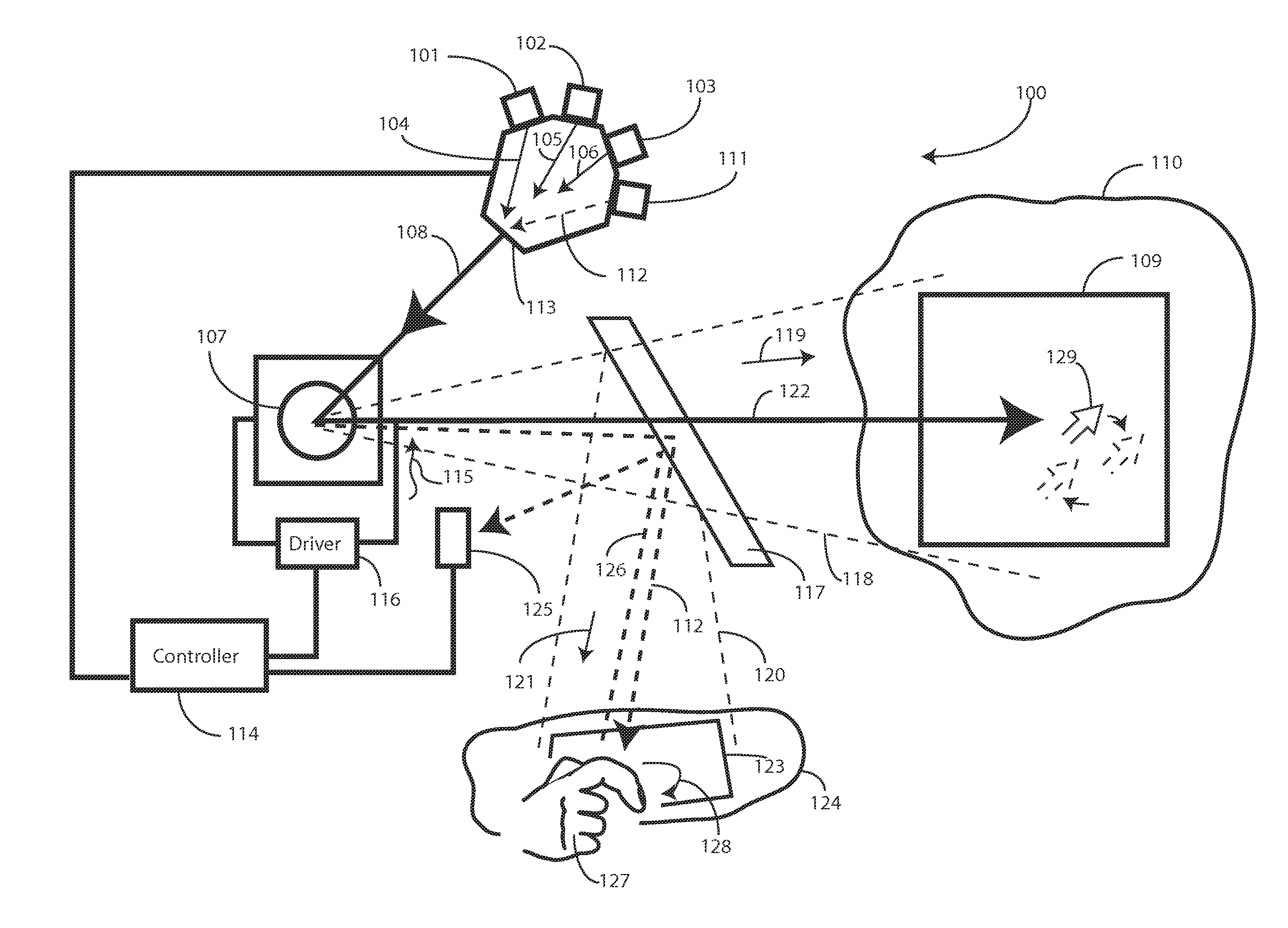
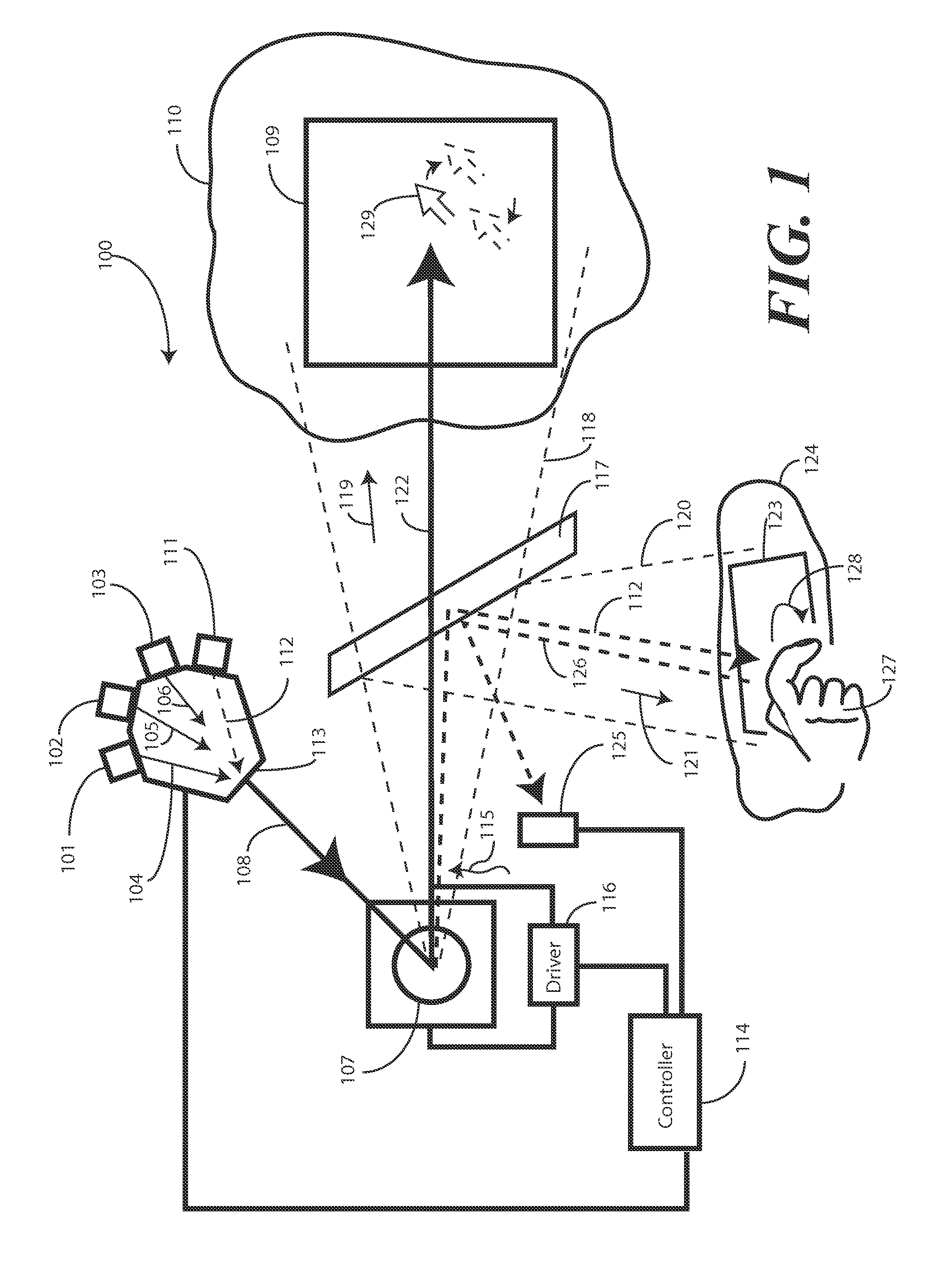
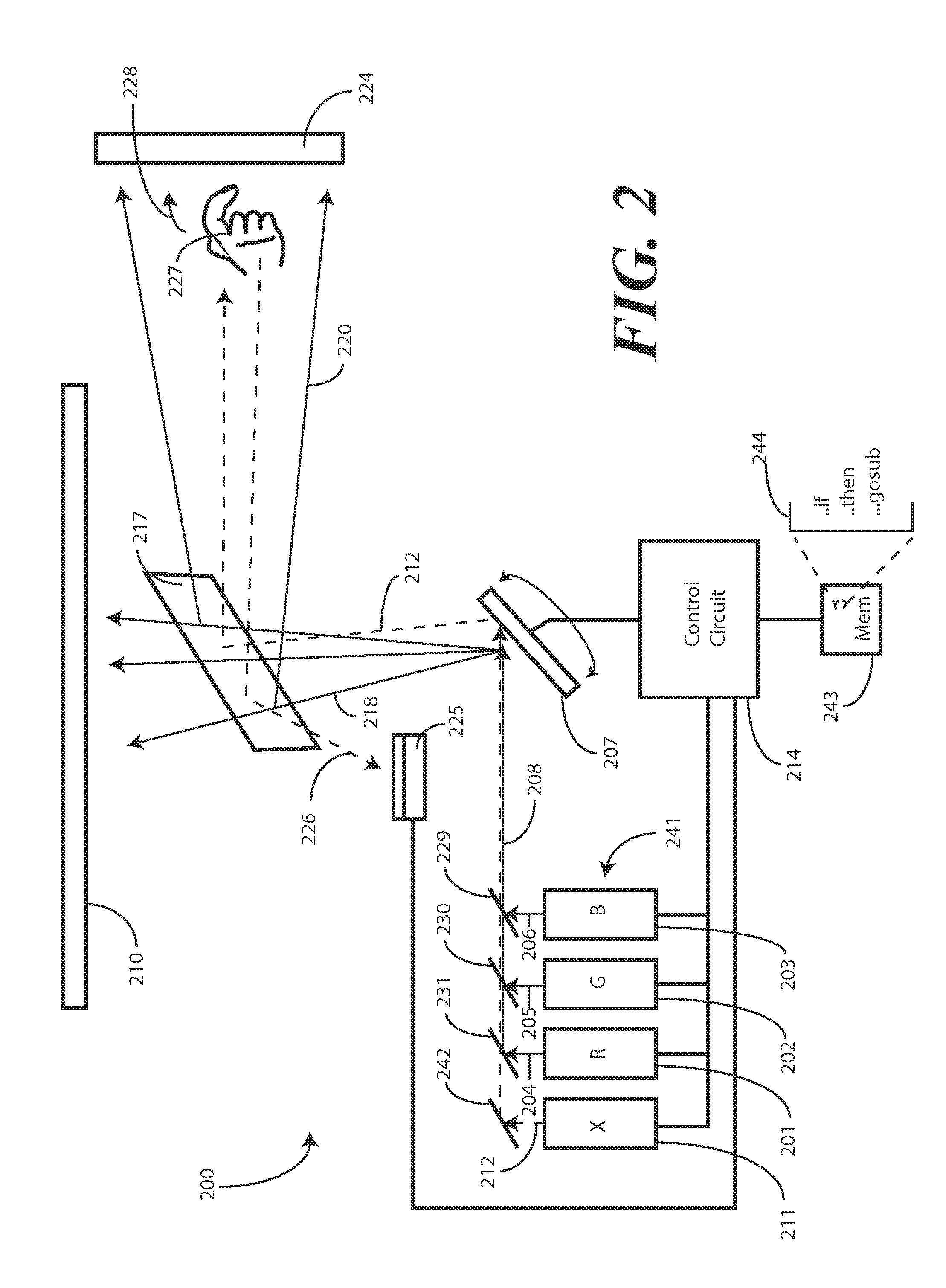
[0018]Before describing in detail embodiments that are in accordance with the present invention, it will be appreciated that embodiments of the invention described herein may be comprised of one or more conventional processors and unique stored program instructions that control the one or more processors to implement, in conjunction with certain non-processor circuits, some, most, or all of the functions of presenting multiple images or permitting a user to control image content as described herein.

[0019]The non-processor circuits may include, but are not limited to, microprocessors, scanning mirrors, image encoding devices, memory devices, clock circuits, power circuits, and so forth. As such, these functions may be interpreted as steps of a method to perform multiple image delivery or image projection system control. It is expected that one of ordinary skill, notwithstanding possibly significant effort and many design choices motivated by, for example, available time, current tech...


PUM


Abstract

An imaging system (100) includes one or more light sources (101,102,103) configured to produce one or more light beams (104,105,106). An additional light source (111) produces an additional light beam (112), which may be a non-visible light beam like an infrared beam. A spatial light modulator (107) is configured to produce images (109) on a projection surface (110) by scanning the light beams and the additional light beam within an image cone (118) oriented in a first direction (119). A partial reflector (117) is disposed within the image cone (118) and is configured to pass at least a portion of the light beams and reflect at least a portion of the additional light beam within a second cone (120) oriented in a second direction (121).

Description

BACKGROUND[0001]1. Technical Field[0002]This invention relates generally to scanned image projection systems, and more particularly to a scanned image projection system employing a beam folder to partially reflect scanned light.[0003]2. Background Art[0004]Scanned image projection systems, such as those employing scanned lasers, facilitate the production of brilliant images created with vibrant colors. These scanned laser projection systems are generally brighter, sharper, and have a larger depth of focus than do conventional projection systems. Further, the advent of semiconductor lasers and laser diodes allows laser projection systems to be designed as compact projection systems that can be manufactured at a reasonable cost. These systems consume small amounts of power yet deliver bright, complex images.[0005]With traditional image projection systems, a presenter making a presentation must face the same projection surface as the audience to view the projected images. This results ...

Claims


Application Information

Patent Timeline
IPC IPC(8): G09G5/00G02B27/01G03B21/28
CPCG02B27/01G02B2027/0187G03B21/2033G03B33/06H04N9/3147G06F3/0304G06F3/0425G09G3/02H04N9/3129G06F3/017
Inventor SPROWL, ROBERT ABROWN, MARGARET K.
Owner MICROVISION
Learn More