Multi-Path Compensation Using Multiple Modulation Frequencies in Time of Flight Sensor

a technology of time flight sensor and modulation frequency, applied in the direction of electromagnetic wave reradiation, measurement device, instruments, etc., can solve the problems of stray light originating from the strong signal adding to the weak signal, and the sensor has to handle high dynamic rang

Active Publication Date: 2012-02-09
AMS SENSORS SINGAPORE PTE LTD
View PDF10 Cites 94 Cited by
  • Summary
  • Abstract
  • Description
  • Claims
  • Application Information

AI Technical Summary

Benefits of technology

[0018]The above and other features of the invention including various novel details of construction and combinations of parts, and other advantages, will now be more particularly described with reference to the accompanying drawings and pointed out in the claims. It will be understood

Problems solved by technology

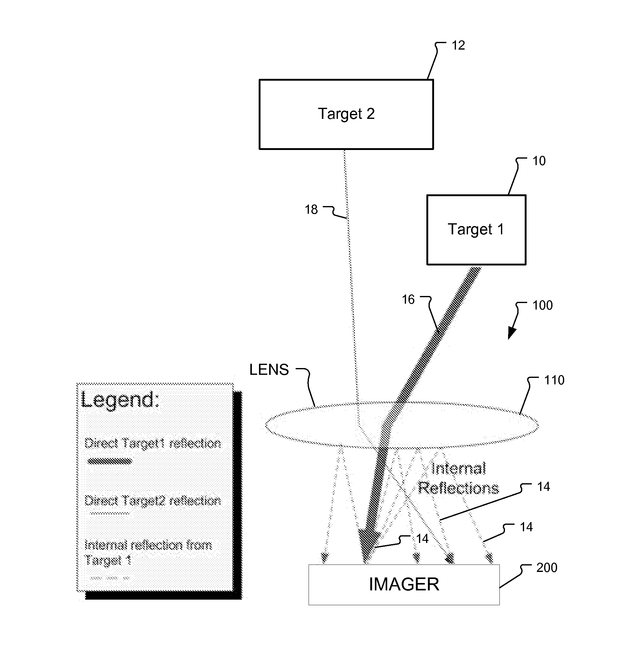
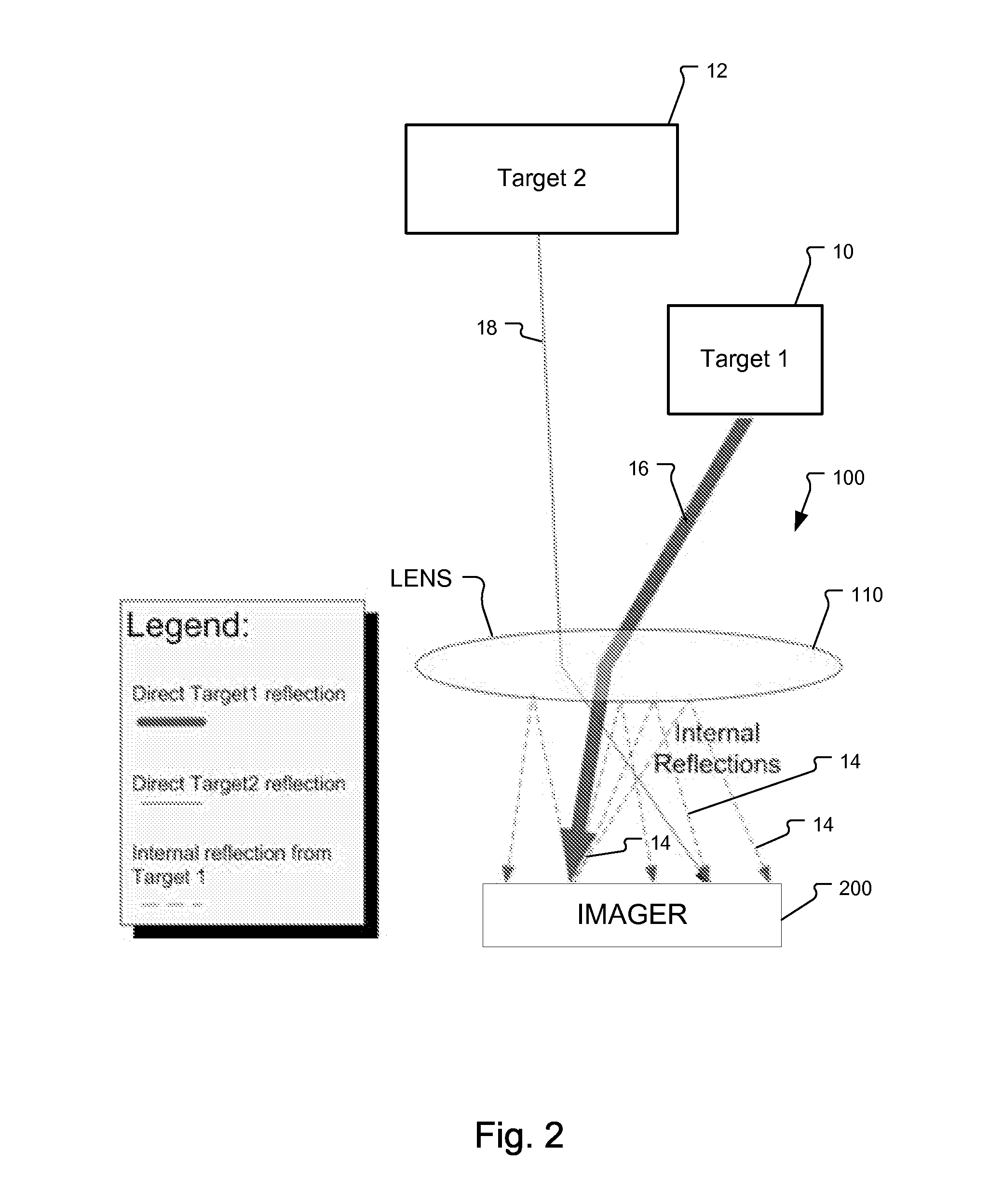
A major problem of a TOF system is that the sensor has to handle high dynamic ranges.
Due to this high requirement on dynamic range, stray light originating from the strong signal adding to the weak signal is a dominant

Method used


Image

  • Multi-Path Compensation Using Multiple Modulation Frequencies in Time of Flight Sensor
  • Multi-Path Compensation Using Multiple Modulation Frequencies in Time of Flight Sensor
  • Multi-Path Compensation Using Multiple Modulation Frequencies in Time of Flight Sensor

Examples


Embodiment Construction

[0028]FIG. 4 illustrates the basic principle of a 3D-measurement camera system 100 based on a sensor 200 comprising a two dimensional array of the demodulation pixels 101.

[0029]Intensity modulated illumination light ML1A at a first modulation frequency from an illumination module or light source IM is sent to the object OB of a scene. A fraction of the total optical power sent out is reflected to the camera 100 and detected by the 3D imaging sensor 200 as reflected light ML2A.

[0030]Each pixel 101 of the sensor 200 is capable of demodulating the impinging light signal ML2 as described above.

[0031]A controller C regulates the timing of the camera 100 so that the demodulation is synchronous with the modulation of light ML1A of the light source IM. The phase values of all pixels correspond to the particular distance information of the corresponding point in the scene. The two-dimension gray scale image with the distance information is converted into a three-dimensional image by the cont...


PUM


Abstract

A method to compensate for multi-path in time-of-flight (TOF) three dimensional (3D) cameras applies different modulation frequencies in order to calculate/estimate the error vector. Multi-path in 3D TOF cameras might be caused by one of the two following sources: stray light artifacts in the TOF camera systems and multiple reflections in the scene. The proposed method compensates for the errors caused by both sources by implementing multiple modulation frequencies.

Description

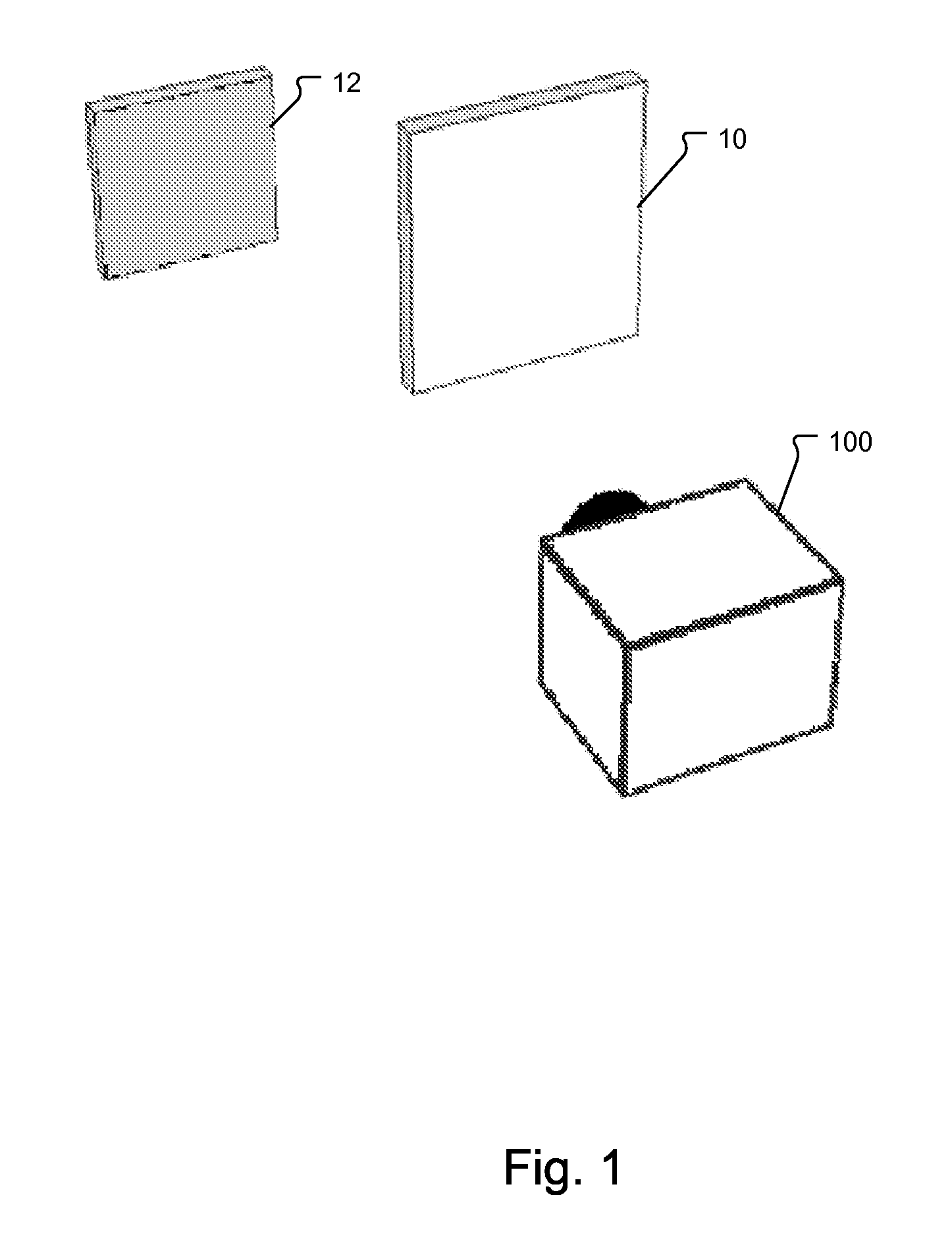
RELATED APPLICATIONS[0001]This application claims the benefit under 35 USC 119(e) of U.S. Provisional Application No. 61 / 367,091, filed on Jul. 23, 2010, which is incorporated herein by reference in its entirety.BACKGROUND OF THE INVENTION[0002]Three dimensional (3D) imaging time-of-flight (TOF) cameras are an active-type system. In general, systems are based on the phase-measurement technique of emitted intensity-modulated light, which is reflected by the scene. The reflected light is imaged onto a sensor. The photo-generated electrons are demodulated in the sensor, and based on the phase information, the distance for each pixel is deduced.[0003]A major problem of a TOF system is that the sensor has to handle high dynamic ranges. The modulated signal received by the camera drops with the square of the distance. Furthermore, the reflectivity of the targets might vary to a large degree.[0004]FIG. 1 illustrates a scene with a high dynamic range. The image detected by TOF camera 100 co...

Claims


Application Information

Patent Timeline
IPC IPC(8): H04N13/02G01S7/4912G01S17/894
CPCG01S17/89G01S7/4912H04N13/207G01S17/894G01S17/36
Inventor SCHWEIZER, MATTHIASOGGIER, THIERRYBUETTGEN, BERNHARD
Owner AMS SENSORS SINGAPORE PTE LTD
Why Eureka
Try Eureka