Tape layout design for reliable ecc decoding

a technology of ecc decoding and layout design, applied in the field of magnetic tape recording, can solve the problem of not optimizing the distance between cwis to achieve an optimum degree of decorrelation, and achieve the effect of reducing the number of errors

Active Publication Date: 2012-02-09
IBM CORP
View PDF2 Cites 13 Cited by
  • Summary
  • Abstract
  • Description
  • Claims
  • Application Information

AI Technical Summary

Benefits of technology

[0018]FIG. 7 is a high-level block diagram showing an example of CWIs of...

Problems solved by technology

One drawback associated with these tape layout schemes is that they do not ...

Method used


Image

  • Tape layout design for reliable ecc decoding
  • Tape layout design for reliable ecc decoding
  • Tape layout design for reliable ecc decoding

Examples


Embodiment Construction

[0025]It will be readily understood that the components of the present invention, as generally described and illustrated in the Figures herein, could be arranged and designed in a wide variety of different configurations. Thus, the following more detailed description of the embodiments of the invention, as represented in the Figures, is not intended to limit the scope of the invention, as claimed, but is merely representative of certain examples of presently contemplated embodiments in accordance with the invention. The presently described embodiments will be best understood by reference to the drawings, wherein like parts are designated by like numerals throughout.

[0026]As will be appreciated by one skilled in the art, the present invention may be embodied as an apparatus, system, method, or computer program product. Furthermore, the present invention may take the form of a hardware embodiment, a software embodiment (including firmware, resident software, microcode, etc.) configure...


PUM


Abstract

A method for physically laying out data on tape is disclosed herein. In one embodiment, such a method includes receiving a data set, wherein the data set includes S sub data sets (SDSs) of fixed size and each SDS includes N codeword interleaves (CWIs). The method further distributes the CWIs for the S SDSs across T tracks on a physical tape medium such that the distances between CWIs of the same SDS are substantially maximized on the physical tape medium. To maximize the distances, the method periodically rotates the tracks within the data set by a track rotation value R, wherein the number of tracks T is equal to 2k, and the track rotation value R is equal to 2k−1−1. A corresponding apparatus is also disclosed herein.

Description

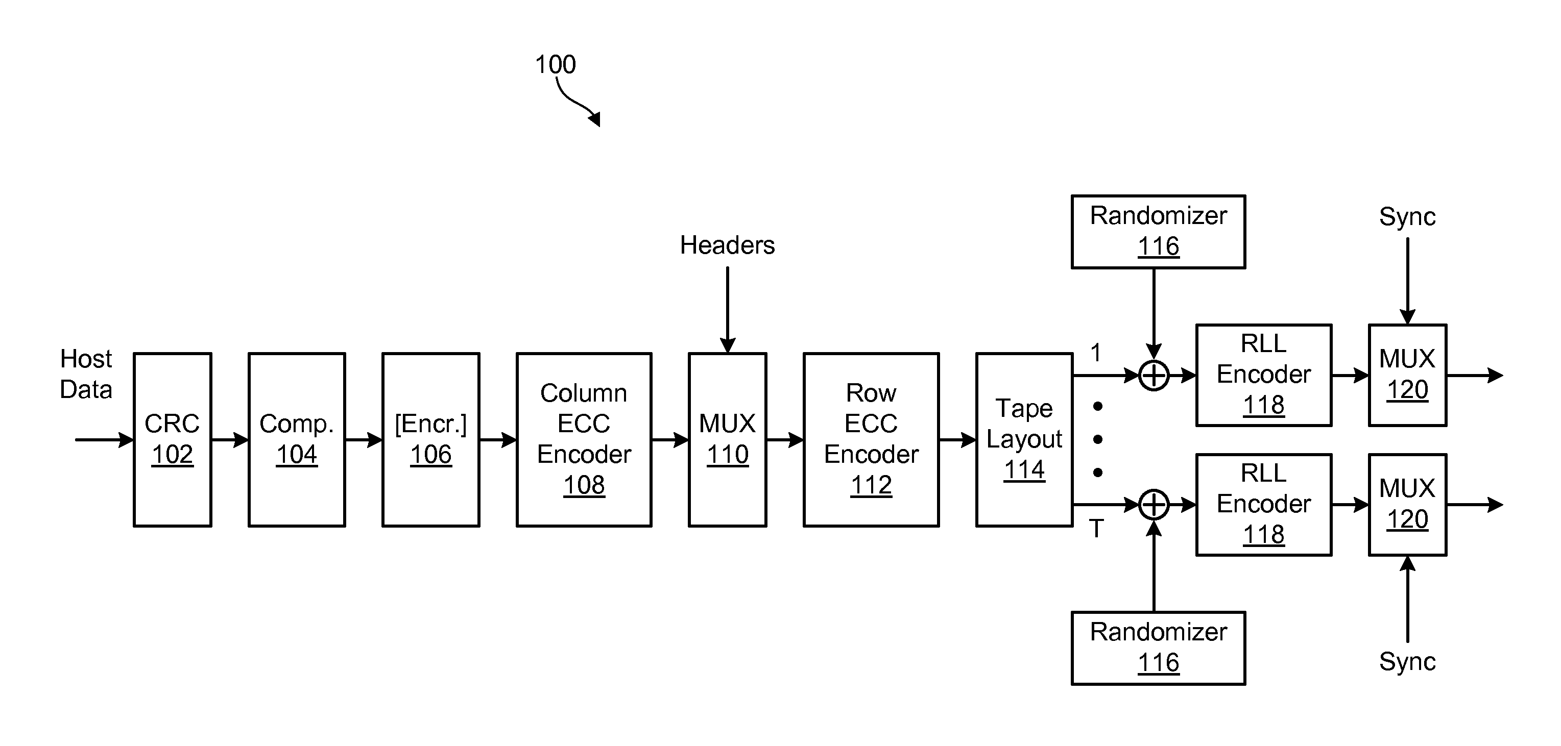
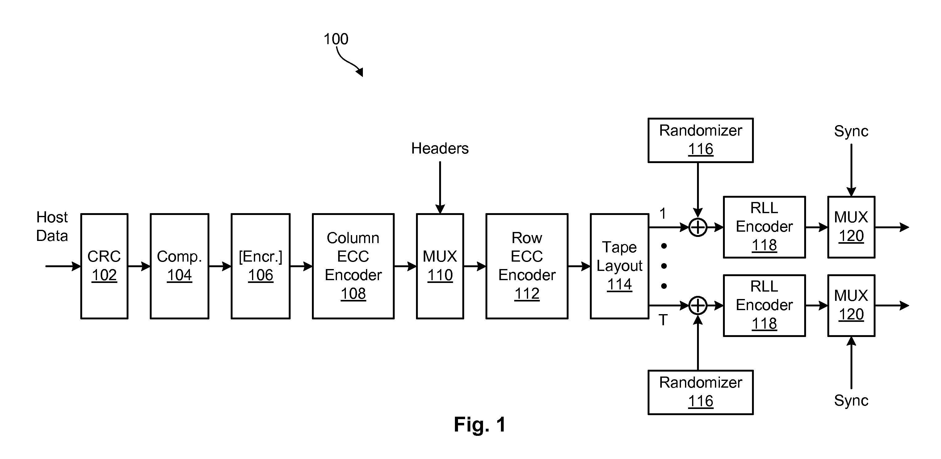
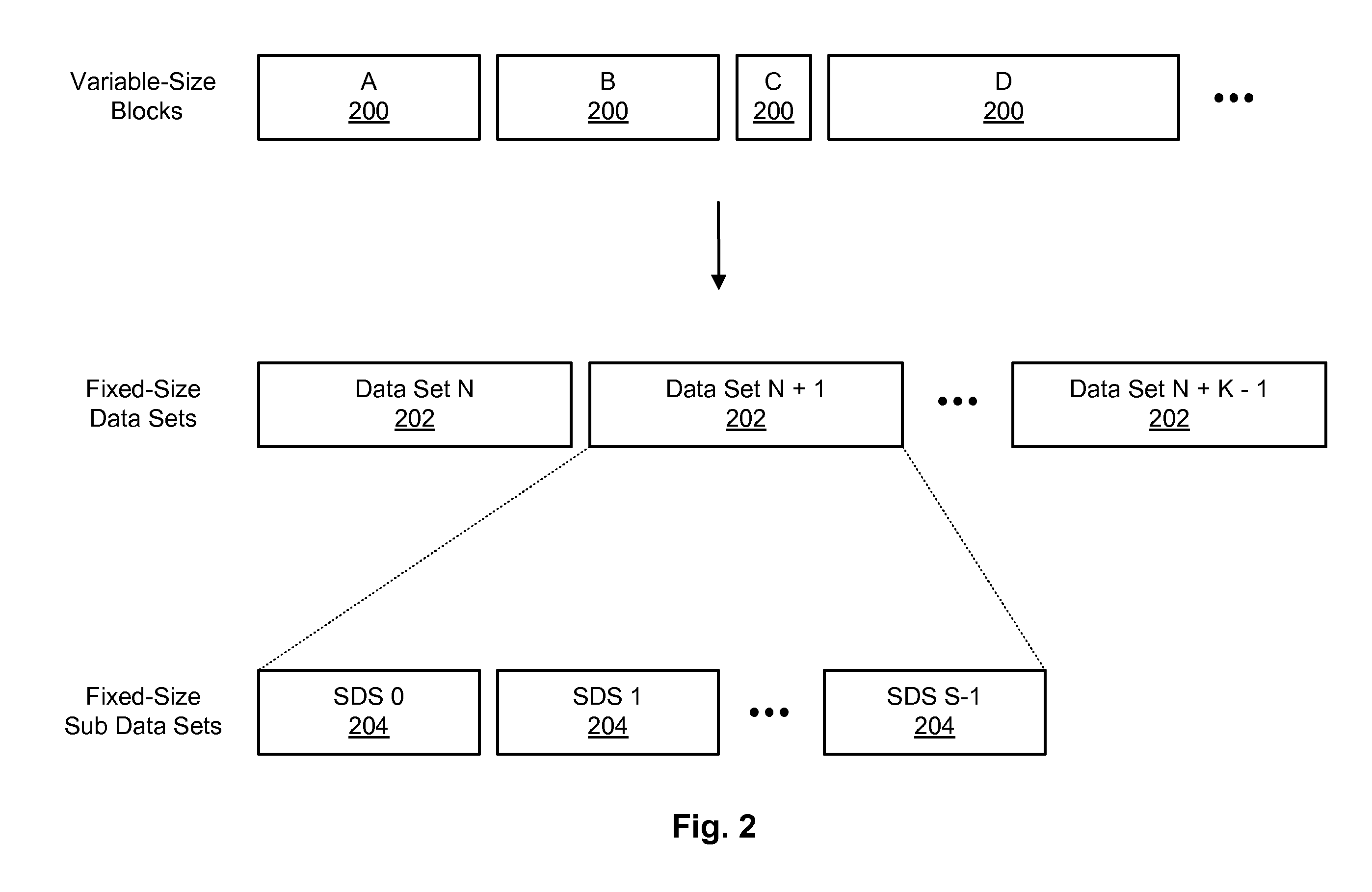
BACKGROUND[0001]1. Field of the Invention[0002]This invention relates to magnetic tape recording, and more particularly to apparatus and methods for laying out data on magnetic tape.[0003]2. Background of the Invention[0004]In some tape drives, such as current LTO and enterprise-level tape drives, variable-length blocks of data are received from a host interface and converted into fixed-size units known as data sets. These data sets are typically broken into smaller fixed-size units known as sub data sets (SDSs). Error correction coding is then generated for each SDS as a unit to protect the data contained therein.[0005]To protect the data in an SDS, conventional tape drives may organize the data in an SDS into a two-dimensional array of rows and columns. Each row in the two-dimensional array may be made up of multiple (e.g., 2 or 4) interleaved data words. Error correction codes (i.e., ECC codes) may then be generated for each row in the array and each column in the array to protec...

Claims


Application Information

Patent Timeline
IPC IPC(8): G11B5/09H03M13/00
CPCG11B5/00817G11B5/09G11B20/1201H03M13/2909G11B2020/1853G11B2220/956G11B20/1866
Inventor CIDECIYAN, ROY D.MITTELHOLZER, THOMASOHTANI, KENJISEGER, PAUL J.TANAKA, KEISUKE
Owner IBM CORP
Why Eureka
Try Eureka