Arrangement for hydrocarbon extraction in wells using progressive cavity pumps

a technology of progressive cavity and hydrocarbon extraction well, which is applied in the direction of machines/engines, liquid fuel engines, borehole/well accessories, etc., can solve the problems of tubing wearing out, poor lubrication, and inability to avoid certain contact and friction between tubing and the rod rotating inside, so as to reduce the wear and corrosion of tubing and reduce the effect of wear and corrosion

Inactive Publication Date: 2012-02-09
COMPANIAS ASOCIADAS PETROLERAS
View PDF8 Cites 13 Cited by
  • Summary
  • Abstract
  • Description
  • Claims
  • Application Information

AI Technical Summary

Benefits of technology

[0002]Within prior art as to this matter, it is worth mentioning that usually in hydrocarbon extraction field wells, power transmission from the surface engine to the bottom pumps “progressive cavity pumps” type, or PCP, is carried out by means of one or more metal rods or bars which rotate inside the metal tubing. As the production well depth may be of several hundred meters or over one thousand meters, it is impossible to avoid certain contact and friction between the tubing and the rods rotating inside it. The progressive cavity pump uses the oil which it pumps from the bottom of the well as a lubricant between the surfaces which suffer this friction, i.e. between the internal face of the tubing and the external face of the rods which rotate along its inside. One of the disadvantages arising from the friction between the bottom pump driving rods and the tubing appears as oil fields grow old, as the secondary recovery process increases the percentage of water in the “water-oil” mixture reaching amounts over 95%, bringing about poor lubrication and, in many cases, a combined situation of tubing wearing out due to friction and corrosion. As a consequence of the reiterated friction between rods and tubing the protective boundary layer breaks up—this layer is formed by the building up of a thin deposit of the hydrocarbon present in water and / or by the artificial injection of certain film coating product used as non-corrosive, should this latter method be used—causing tubing corrosion and wearing out. Therefore, it is extremely important to solve this serious problem as it causes considerable economic losses, clearly enough, as exploitation processes at oil fields must be interrupted until tubings are repaired or replaced.
[0003]With the aim of solving the above mentioned problems, the arrangement subject matter of this invention has been developed, it allows to considerably reduce the tubings' “wearing out-corrosion-wearing out” combined problem, as it shall be explained below in the “how to put it into practice” proposal.
[0004]The purpose of this invention is to provide an arrangement for hydrocarbon extraction in wells using progressive cavity pumps, this arrangement was developed with the aim of reducing wearing out as a result of friction and corrosion in conventional tubings used in field wells in which the extraction of fluids is carried out by means of progressive cavity pumps. This arrangement consists of a rotating tube located inside a fixed tube placed along the well casing. The rotating tube carries the fluid from the bottom of the well to the surface. Between the rotating tube and the fixed tube there is an “O” ring-type space into which an anti-friction lubricant is injected between the external face of the rotating tube and the internal face of the fixed tube. The bottom end of the rotating tube has a section with holes which allow fluids to flow into it and it is connected to the progressive cavity pump by means of a rod, its top end is connected to a production outlet and to its propelling motor mechanism. The upper section of the fixed tube is connected to an anti-friction lubricant injection pipe in the space left between the rotating tube and the fixed tube.

Problems solved by technology

As the production well depth may be of several hundred meters or over one thousand meters, it is impossible to avoid certain contact and friction between the tubing and the rods rotating inside it.
One of the disadvantages arising from the friction between the bottom pump driving rods and the tubing appears as oil fields grow old, as the secondary recovery process increases the percentage of water in the “water-oil” mixture reaching amounts over 95%, bringing about poor lubrication and, in many cases, a combined situation of tubing wearing out due to friction and corrosion.
Therefore, it is extremely important to solve this serious problem as it causes considerable economic losses, clearly enough, as exploitation processes at oil fields must be interrupted until tubings are repaired or replaced.

Method used


Image

  • Arrangement for hydrocarbon extraction in wells using progressive cavity pumps
  • Arrangement for hydrocarbon extraction in wells using progressive cavity pumps
  • Arrangement for hydrocarbon extraction in wells using progressive cavity pumps

Examples


Embodiment Construction

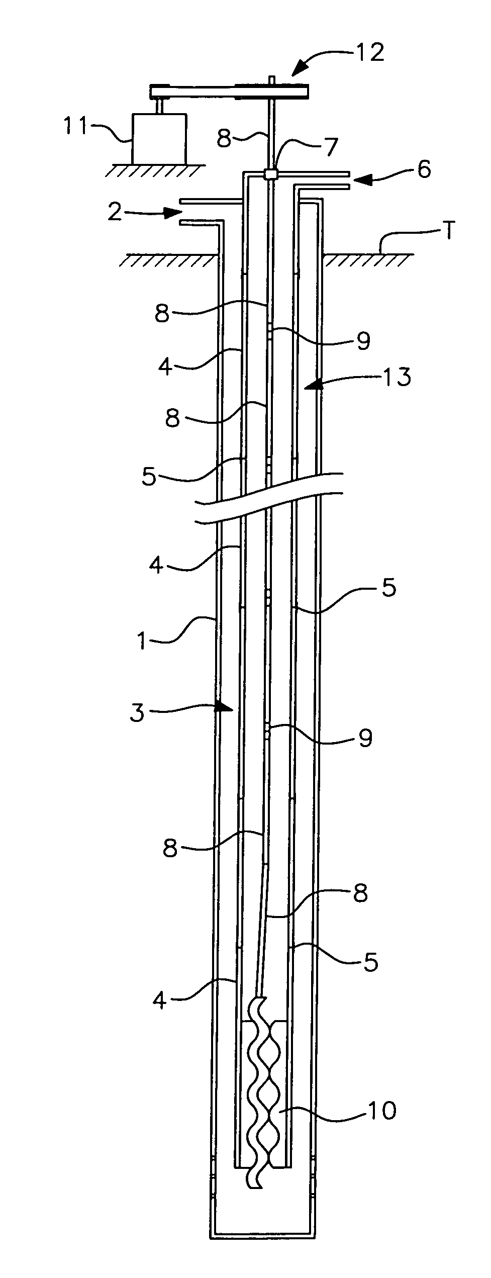
[0010]FIG. 1 shows that the illustrated example of a conventional pumping arrangement consists of a casing 1, with a wellhead outlet 2, which holds inside a tubing 3, which carries the fluid from the bottom of the well to the surface, formed by a succession of sections 4 connected among them by joints 5. Between the casing 1 and the tubing 3 there is a longitudinally defined “O” ring-type space 13. The upper section 4 of the tubing 3 which projects itself from the wellhead at the field's land T surface has a production outlet 6, through which the first of a succession of rods 8 connected among them by joints 9 passes as well as through a stuffing box 7, the last rod 8 at the tubing's lower section 4 is connected to a bottom PCP pump 10. In order to drive the rotating movement of the group of rods 8, and consequently to drive the pump 10, the upper rod 8 is connected to an electric engine 11 by means of a belt-and-pulley transmission mechanism 12.

[0011]As it has already been stated, ...


PUM


Abstract

Arrangement for hydrocarbon extraction in wells using progressive cavity pumps which consists of a rotating tube located inside a fixed tube which extend along the well casing. The rotating tube carries fluid from the bottom of the well to the surface. Between the rotating tube and the fixed tube there is an “O” ring space into which an anti-friction lubricant is injected between the external face of the rotating tube and the internal face of the fixed tube. The bottom end of the rotating tube has a section holding holes through which fluid flows into it, it is connected to the progressive cavity pump by means of a rod, and its top end is connected to a production outlet and to its propelling motor mechanism. The upper section of the fixed tube is connected to an anti-friction lubricant injection pipe in the space left between the rotating and the fixed tubes. This arrangement prevents the wearing out, as a result of friction and corrosion, of conventional tubings used in field wells where fluid extraction is carried out by means of progressive cavity pumps.

Description

FIELD OF THE INVENTION[0001]This invention refers to an arrangement for hydrocarbon extraction in wells using progressive cavity pumps, and more in particular it relates to an oil extraction tubing arrangement developed in order to reduce its wearing out as a result of friction and corrosion in field wells in which progressive cavity pumps or “PCP” are used.PRIOR ART AND ADVANTAGES OF THE INVENTION[0002]Within prior art as to this matter, it is worth mentioning that usually in hydrocarbon extraction field wells, power transmission from the surface engine to the bottom pumps “progressive cavity pumps” type, or PCP, is carried out by means of one or more metal rods or bars which rotate inside the metal tubing. As the production well depth may be of several hundred meters or over one thousand meters, it is impossible to avoid certain contact and friction between the tubing and the rods rotating inside it. The progressive cavity pump uses the oil which it pumps from the bottom of the we...

Claims


Application Information

Patent Timeline
Patent Type & Authority Applications(United States)
IPC IPC(8): F01C1/10
CPCE21B43/126E21B17/1078
Inventor DEL POZO, LEONCIO
Owner COMPANIAS ASOCIADAS PETROLERAS
Why Eureka
Try Eureka