Systems, Apparatuses, and Methods for Using Durable Adhesively Bonded Joints for Sandwich Structures

a technology of durable adhesive and sandwich structure, which is applied in the field of systems, apparatuses and methods for using durable adhesively bonded joints for sandwich structures, can solve the problems of reducing the load carrying capacity of the adhesive joint, the failure of the adhesive and the surface, etc., and achieves the reduction of the structural fatigue of the first splice, the effect of increasing the durability of the adhesively bonded joint and reducing the structural fatigue of the second spli

Inactive Publication Date: 2012-02-09
NASA
View PDF1 Cites 1 Cited by
  • Summary
  • Abstract
  • Description
  • Claims
  • Application Information

AI Technical Summary

Benefits of technology

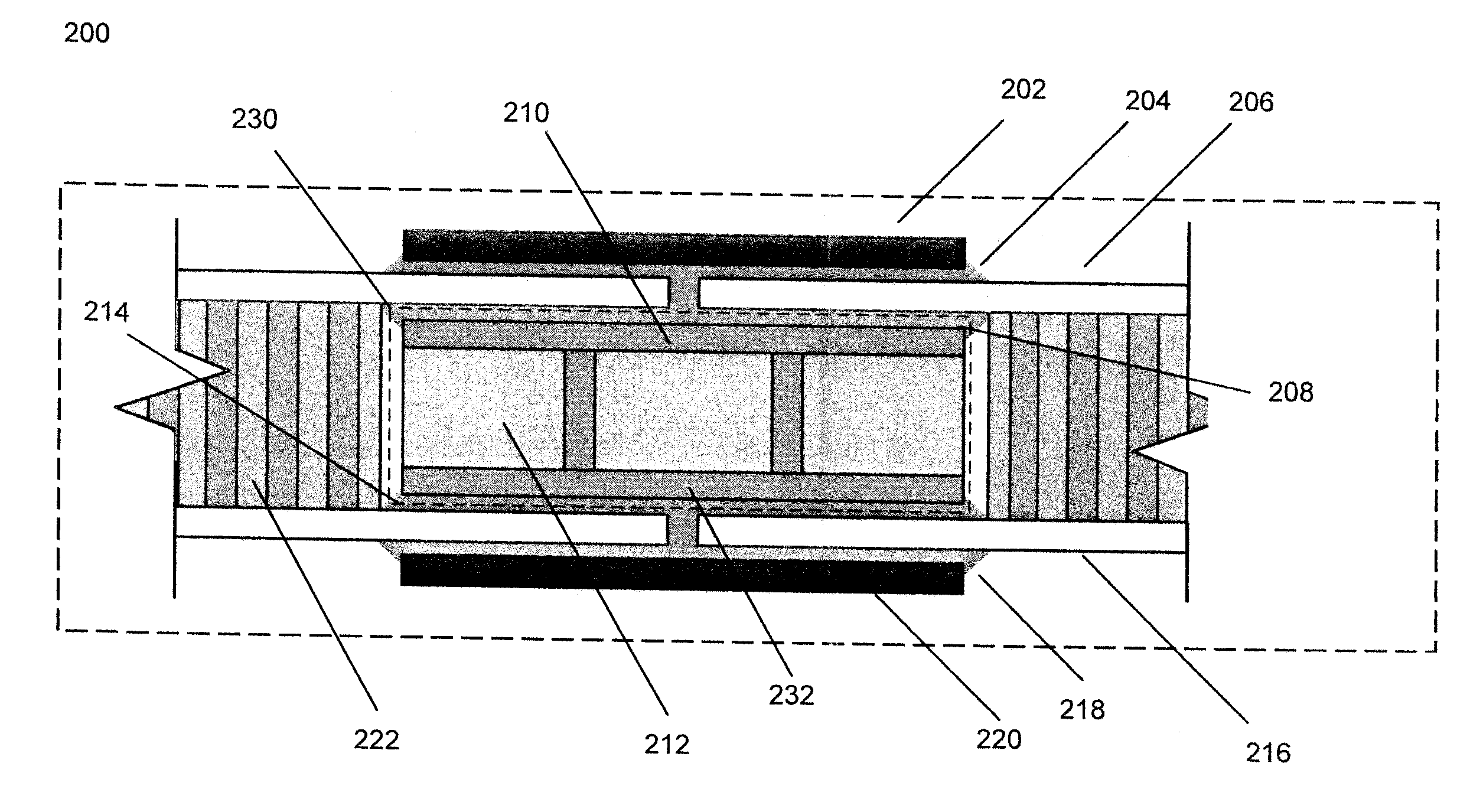
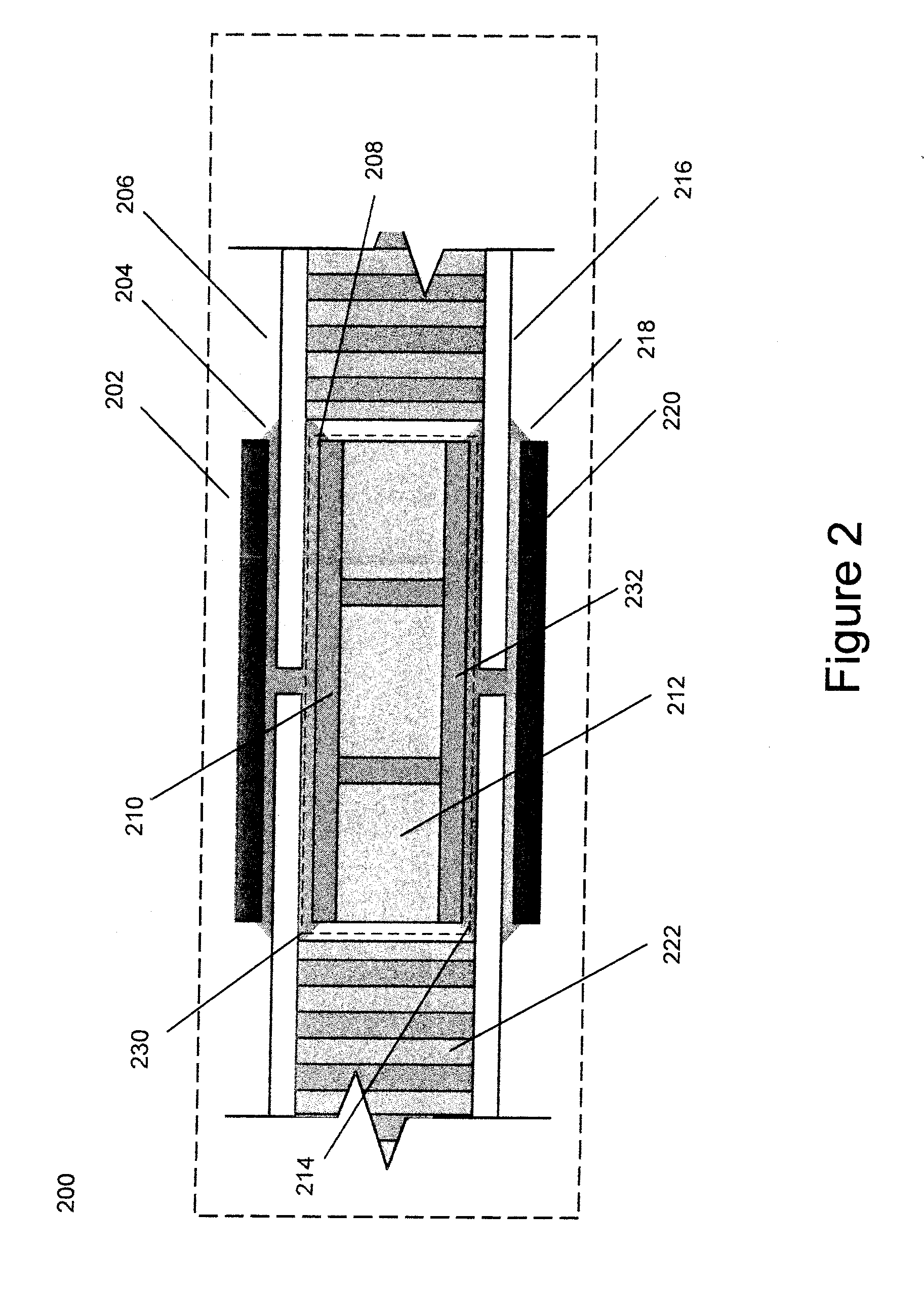
[0007]Further, the exemplary apparatus may include the first redundant bondline providing a redundant load path for the load in the first face sheet. Further, the apparatus may include the second redundant bondline provides a redundant load path for the load in the second face sheet. In addition, a first redundant bondline is capable of reducing structural fatigue of the first splice of the joint by redistributing the load on the first primary bondline to the first redundant bondline and the insert structure. Also, the second redundant bondline is capable of reducing structural fatigue of the second splice of joint by redistributing the load on the second primary bondline to the second redundant bondline and the insert structure.
[0008]Additional embodiments of the present disclosure may include a system for increasing durability of adhesively bonded joints in a sandwich structure. Such a system may include one or more sandwich structures each sandwich structure having a first face sheet and a second face sheet as well as an insert structure. The insert structure having a first insert face sheet, a second insert face sheet, and an insert core material. Further, the system may include sandwich core material arranged between the first face sheet and the second face sheet, the core having a recessed area capable of holding a portion of the insert structure. The first face sheet may be coupled to a first splice by a first primary bondline and the first face sheet may be coupled to the first insert face sheet by a first redundant bondline. In addition, the second face sheet may be coupled to a second splice by a second primary bondline and the second face sheet may be coupled to the second insert face sheet by a second redundant bondline. The first redundant bondline reduces load on the first primary bondline and the second redundant bondline reduces a load on the second primary bondline.
[0009]Further, the system may include one or more insert structures, each coupled and substantially perpendicular to both the first insert face sheet and the second insert face sheet. Also, an adhesive fillet may be included in the first primary bondline, the first redundant bondline, the second redundant bondline, and the second primary bondline. The first redundant bondline provides a redundant load path for the load on the first primary bondline and the second redundant bondline provides a redundant load path for the load on the second primary bondline. In addition, first redundant bondline is capable of reducing structural fatigue of the joint by redistributing the load from the first splice to first face sheet of insert and the insert structure. Comparatively, the second redundant bondline is capable of reducing structural fatigue of the joint by redistributing the load on the second primary bondline to second redundant bondline and the insert structure.

Problems solved by technology

However, adhesive bonded joints are susceptible to manufacturing defects that result in a failure between the adhesive and a surface.
Such manufacturing defects may significantly decrease the load carrying capability of the adhesive joint.

Method used


Image

  • Systems, Apparatuses, and Methods for Using Durable Adhesively Bonded Joints for Sandwich Structures
  • Systems, Apparatuses, and Methods for Using Durable Adhesively Bonded Joints for Sandwich Structures
  • Systems, Apparatuses, and Methods for Using Durable Adhesively Bonded Joints for Sandwich Structures

Examples


Embodiment Construction

[0023]In the following detailed description, reference is made to the accompanying drawings, which for a part hereof. In the drawings, similar symbols typically identify similar components, unless context dictates otherwise. The illustrative embodiments described in the detailed description, drawings, and claims are not meant to be limiting. Other embodiments may be utilized, and other changes may be made, without departing from the spirit or scope of the subject matter presented herein. It will be readily understood that the aspects of the present disclosure, as generally described herein, and illustrated in the Figures, can be arranged, substituted, combined, separated, and designed in a wide variety of difference configurations, all of which are explicitly contemplated herein. Further, in the following description, numerous details are set forth to further describe and explain one or more embodiments. These details include system configurations, block module diagrams, flowcharts ...


PUM

PropertyMeasurementUnit
diameteraaaaaaaaaa
durabilityaaaaaaaaaa
areaaaaaaaaaaa

Abstract

Systems, methods, and apparatus for increasing durability of adhesively bonded joints in a sandwich structure. Such systems, methods, and apparatus includes an first face sheet and an second face sheet as well as an insert structure, the insert structure having a first insert face sheet, a second insert face sheet, and an insert core material. In addition, sandwich core material is arranged between the first face sheet and the second face sheet. A primary bondline may be coupled to the face sheet(s) and the splice. Further, systems, methods, and apparatus of the present disclosure advantageously reduce the load, provide a redundant path, reduce structural fatigue, and/or increase fatigue life.

Description

CROSS-REFERENCE TO RELATED APPLICATIONS[0001]The present application claims priority under the laws and rules of the United States, including 35 USC §120, to U.S. Provisional Patent Application No. 61 / 370,853 filed on Aug. 5, 2010. The contents of U.S. Provisional Patent Application No. 61 / 370,853 are herein incorporated by reference.STATEMENT REGARDING FEDERALLY SPONSORED RESEARCH AND DEVELOPMENT[0002]This invention was made in part with Government support. The Government may have certain rights in this invention.BACKGROUND[0003]Heavy lift cargo vehicles including aerospace vehicles such as rocket launch vehicles can be made of composite materials. Composite technology used in such heavy lift cargo vehicles may use adhesive bonded joints or mechanically fastened (bolted) configurations to join one or more composite panels or structures. Adhesively bonded joints are efficient joining methods for launch vehicle structures compared with mechanically fastened (bolted) configurations. ...

Claims


Application Information

Patent Timeline
Patent Type & Authority Applications(United States)
IPC IPC(8): B32B3/06B32B37/12B32B37/14B32B3/08
CPCF16B11/006Y10T428/183B64G1/002B64G1/66B32B37/02Y10T428/19Y10T428/192Y10T428/18Y10T428/24025Y10T156/10Y10T428/17B32B37/12
Inventor SMELTZER, III, STANLEY S.LUNDGREN, ERIC C.
Owner NASA
Why Eureka
Try Eureka