Capacitive switch reference method

a capacitive switch and reference method technology, applied in the field of capacitive switches, can solve the problems of nonresponsiveness, false triggering, electrical noise, etc., and achieve the effect of reducing the risk of electrical noise, reducing the reliability of the capacitive switch, and reducing the cost of the switch

Active Publication Date: 2012-02-16
TOYOTA MOTOR CO LTD
View PDF8 Cites 72 Cited by
  • Summary
  • Abstract
  • Description
  • Claims
  • Application Information

AI Technical Summary

Benefits of technology

[0005]For example, in the case of a finger-operated capacitive switch, both the reference signal level and switch sensor level (in each case, when a finger is close) are correlated with certain physical properties of the finger. These properties include skin electrical conductivity, finger dimensions, the presence of a glove or other covering, and the like. Hence, by adjusting the threshold signal level as a function of the capacitive reference signal, improved operation of the capacitive switch can be obtained. The effects of the aforementioned finger physical properties on switch operation can be appreciably reduced.

Problems solved by technology

However, conventional capacitive switches are prone to a variety of problems, such as nonresponsiveness, false triggering, and electrical noise.

Method used


Image

  • Capacitive switch reference method
  • Capacitive switch reference method
  • Capacitive switch reference method

Examples


Embodiment Construction

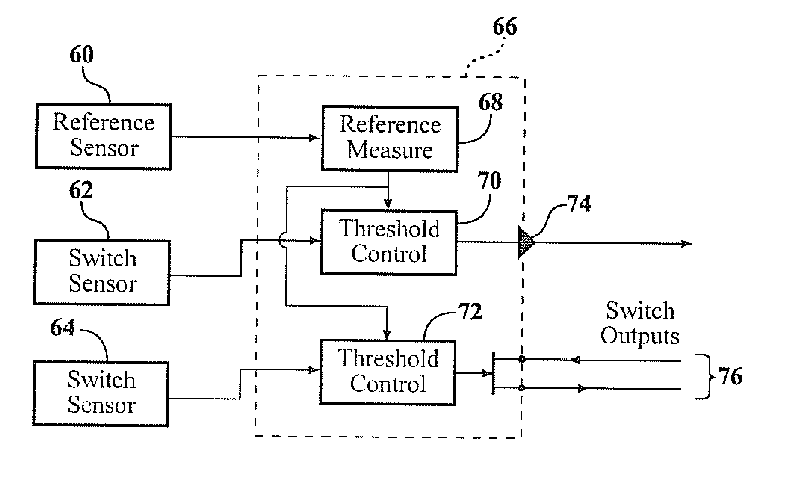
[0024]A conventional capacitive switch may comprise a capacitive switch sensor providing a sensor signal and an electronic circuit receiving the sensor signal. The electronic circuit uses a predetermined threshold to determine when the sensor signal corresponds to an “activated” state

[0025]However, the sensor response depends on a number of factors, such as the size, conductivity, and physical state of e.g. a finger used to operate the switch. For example, a gloved hand may give a much smaller change in sensor signal, if a gloved finger is used to activate the switch.

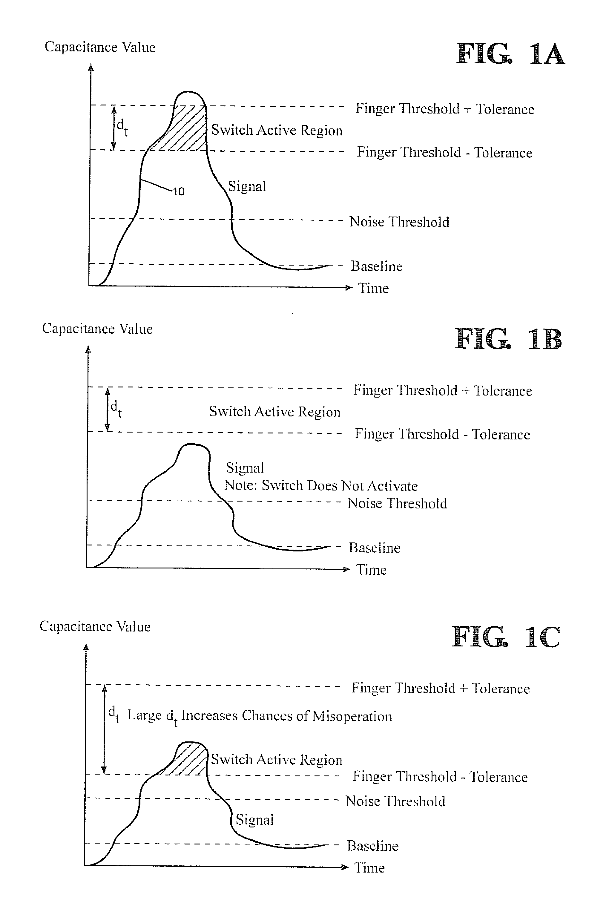
[0026]The threshold used may have a tolerance, and broadening the tolerance allows smaller changes in the sensor signal to be registered as switch activation. However, this also makes the switch more sensitive to false operation, or misdetection of switch activation.

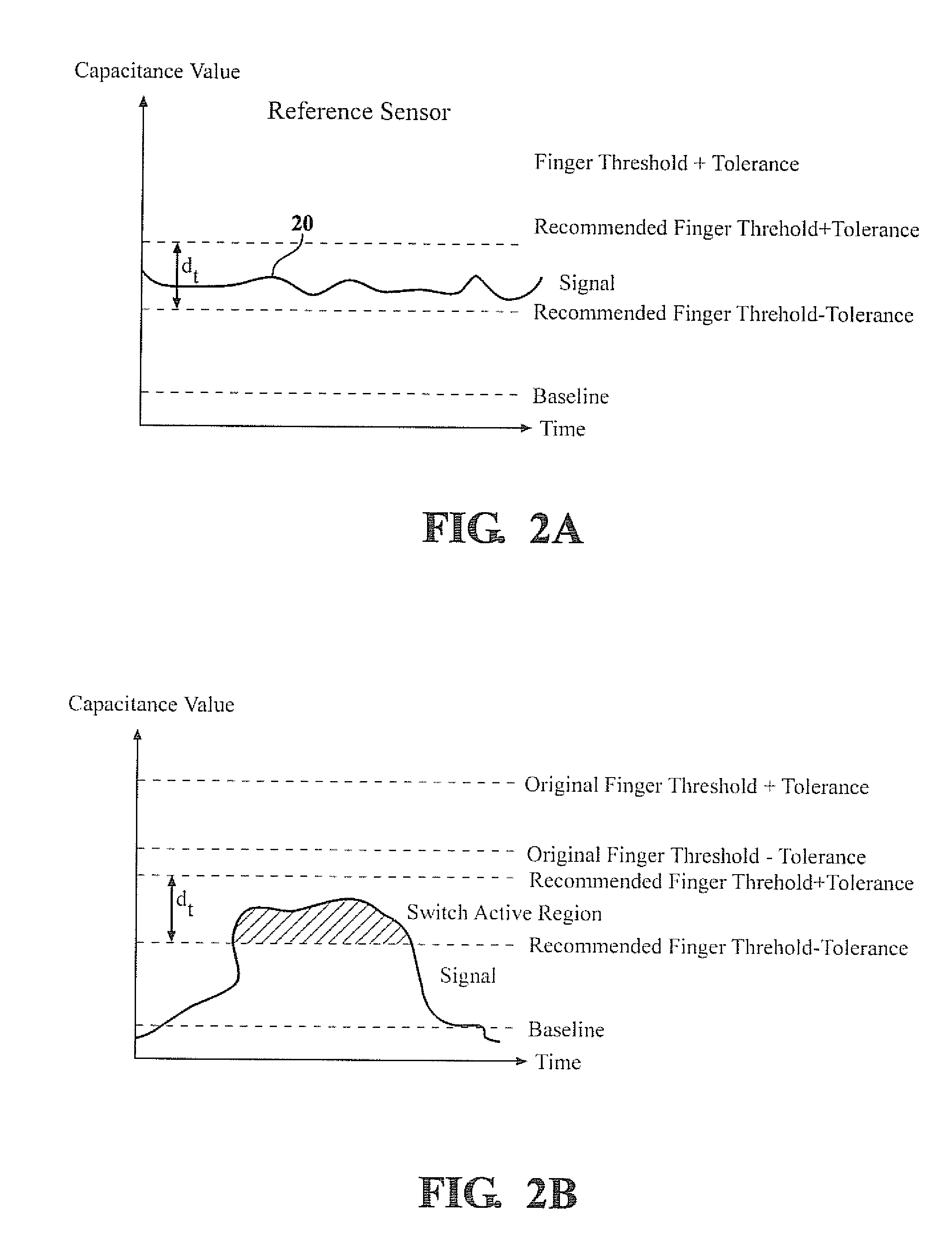
[0027]Hence, the optimum threshold level may vary considerably according to electrical parameters an operator's hand, such as skin conductivity, finger size...


PUM


Abstract

An example capacitive switch apparatus comprises a capacitive switch sensor providing a capacitive switch signal, a capacitive reference sensor providing a capacitive reference signal, and an electronic circuit, receiving the switch and reference signals and detecting switch activation by comparing the switch signal level with a threshold level. The threshold level is adjusted as a function of the reference signal level. The reference signal is obtained, for example during periods of operator proximity to the reference sensor. For a finger-operated switch, the reference signal is obtained when a finger is proximate the reference sensor.

Description

FIELD OF THE INVENTION[0001]The invention relates to electrical switches, in particular to capacitive switches.BACKGROUND OF THE INVENTION[0002]Capacitive switches can replace mechanical switches in a variety of applications. However, conventional capacitive switches are prone to a variety of problems, such as nonresponsiveness, false triggering, and electrical noise.SUMMARY OF THE INVENTION[0003]Examples of the present invention include apparatus and methods related to an improved capacitive switch.[0004]An example apparatus comprises a switch sensor, a reference sensor, and an electronic circuit receiving a sensor signal from the switch sensor and a reference signal from the reference sensor. The electronic circuit detects switch operation when the sensor signal crosses a threshold signal level. The threshold signal level is adjusted as a function of the reference signal, allowing improved operation of the capacitive switch. The electronic circuit used to adjust the threshold sign...

Claims


Application Information

Patent Timeline
Patent Type & Authority Applications(United States)
IPC IPC(8): H03K17/975
CPCH03K17/955H03K17/962H03K2217/94021H03K2217/96073
Inventor SITARSKI, NICHOLAS SCOTT
Owner TOYOTA MOTOR CO LTD
Why Eureka
Try Eureka