Method for Discontinuously Emptying a Container

a container and discontinuous technology, applied in the direction of liquid transfer devices, instruments, liquid handling, etc., can solve the problems of requiring comparatively high resources, affecting the effect of emptying, and requiring a large amount of resources, so as to achieve convenient and fast emptying, convenient operation, and convenient operation

Inactive Publication Date: 2012-02-16
DAIMLER AG
View PDF5 Cites 11 Cited by
  • Summary
  • Abstract
  • Description
  • Claims
  • Application Information

AI Technical Summary

Benefits of technology

[0015]Particularly when the possibility exists of using a rather large container in comparison with the volume of liquid arising, this can be decisively advantageous as a frequent switching of the emptying means can be correspondingly prevented. In particular, the variation of time also offers the possibility of integrating the system into existing containers. as through a corresponding adjustment of the time, for example in a test operation under extreme conditions, a reliable operation can be achieved without having to change the construction of the container itself.
[0016]In a further particularly advantageous embodiment of the inventive method it is further provided that a capacitive sensor is used as the sensor. In comparison with other fill level sensors, such as for example float switches, such a capacitive sensor, which is known in principle from the prior art, offers the advantage that it has a simple construction and manages without corresponding mechanical means. It can thus detect a change in state comparatively simply and reliably even under extreme conditions.

Problems solved by technology

A disadvantage with these types of sensors is that they require comparatively high resources and are expensive.
Due to the fact that both a valve and also a pump as an emptying means are mechanical components which have a certain reaction time and that the emptying means is connected to the container via corresponding line sections or volumes, a certain delay arises between the detection of the state by the sensor and the start of activation of the emptying means or the stopping of the activation of the emptying means.
However, a certain time passes until the mechanical stop of the emptying means arises and the emptying actually ends.
This is also encumbered with a certain delay due to the system, so that the liquid level in the container increases further beyond the sensor until the actual activation of the emptying means starts.
The liquid could block corresponding gas channels or similar there and / or wet them and impair the functionality of the system in the long term.
Due to the limited construction space in a transport means the fuel cell system and in particular the liquid separators can thereby not be constructed in any desired size.
With correspondingly small liquid separators the two abovementioned problems of overflowing and discharge of gas to the environment are particularly critical, however, as correspondingly small containers of the liquid separators require frequent discontinuous emptying.

Method used


Image

  • Method for Discontinuously Emptying a Container
  • Method for Discontinuously Emptying a Container

Examples


Embodiment Construction

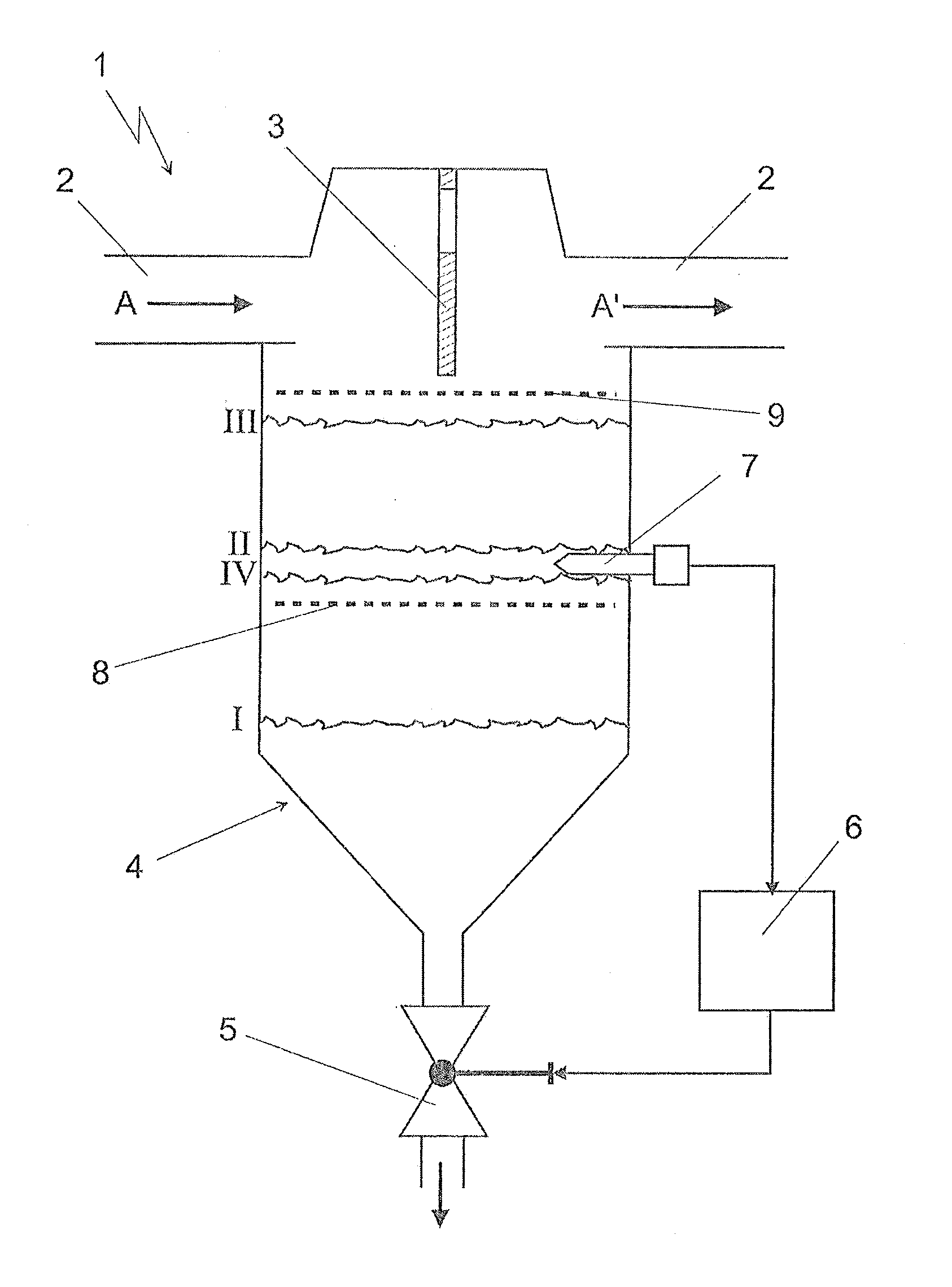
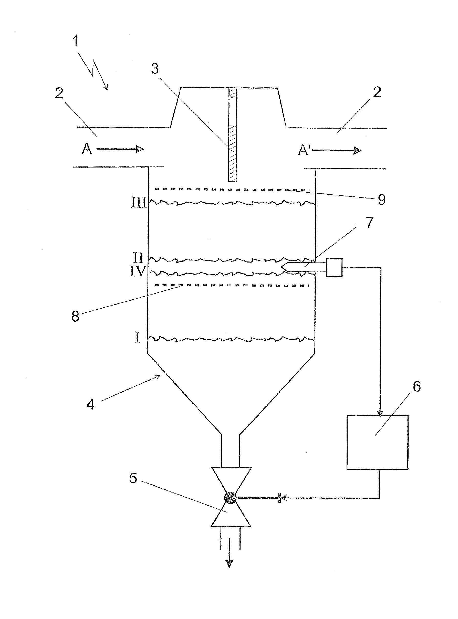
[0022]The drawing shows a schematically represented liquid separator 1, as can be used for example in a fuel cell system in a vehicle. The liquid separator 1 is arranged for this application in particular in the region of the cathode waste gas and / or the anode waste gas and separates liquid product water from the region of these waste gases. This is to be symbolized here through the line element 2, in which—as indicated by the arrow A—a gas is to flow together with condensed liquid. The gas then leaves the liquid separator 1 as gas A′ without liquid components. The liquid is correspondingly separated in the region of a baffle plate 3 while the gas A flows by this baffle plate 3 and / or undergoes a change in direction. The structure with the baffle plate is thereby selected purely by way of example. All other types of separating mechanisms can also be realized, for example a circulating gas flow, wherein the liquid particles are expelled outwards. This is of less importance, however, ...


PUM


Abstract

A method serves for discontinuously emptying a container in which liquid collects. The container is emptied via a valve or other such emptying device. The container must never be completely emptied and never overflow. A sensor is arranged in the container to detect a first state in which liquid is present in a predetermined region and a second state in which no liquid is present in the predetermined region. The valve or other emptying device is activated as soon as the sensor detects the first state, and is stopped as soon as the sensor detects the second state.

Description

BACKGROUND AND SUMMARY OF THE INVENTION[0001]The invention relates to a method for discontinuously emptying a container in which liquid collects via a valve or equivalent structure.[0002]Containers in which liquid collects and which must be emptied from time to time are known in the art. Reference can be made in this connection for example to liquid separators which typically separate liquids carried along by gas flows, for example in the form of droplets, from the gas flow. The separated liquid collects in a container of the liquid separator. From time to time, this liquid must be emptied in order to prevent overflowing of the container. Particularly when the liquid is separated from gases which may not be discharged to the environment for safety reasons, the discontinuous emptying of the container must take place so that the container does not overflow in order to avoid transporting liquid back into the gas flow and so that the container is never completely emptied upon emptying i...

Claims


Application Information

Patent Timeline
Patent Type & Authority Applications(United States)
IPC IPC(8): B67D7/06
CPCG01F23/0007G01F23/241G01F23/261G01F23/265
Inventor MAZZOTTA, COSIMO
Owner DAIMLER AG
Why Eureka
Try Eureka