Supercharge Your Innovation With Domain-Expert AI Agents!

Dispensing liquid containing material to patterned surfaces using a dispensing tube

Inactive Publication Date: 2012-02-16
1366 TECH INC
View PDF9 Cites 6 Cited by
  • Summary
  • Abstract
  • Description
  • Claims
  • Application Information

AI Technical Summary

Benefits of technology

[0004]Liquids, slurries and pastes and other of materials that contain liquid are deposited into grooves or along other physical work piece paths upon a surface of a work piece, such as a silicon wafer that will be used to form a solar collecting cell. Liquid can be dispensed into grooves in which will be formed thin metallization finger elements, under pressure through a fine dispensing capillary tube, which is mechanically guided and aligned by following topography/surface texture on the work piece surface. The dispensing capillary tube mechanically tracks in the groove. The dispensing capillary may be small enough that it rests at the groove bottom, with the groove sidewalls providing tracking restraint. Or, the dispensing capillary may be larger than the groove and may ride on the top edges of the groove, still achieving mechanical alignment. A tracking feature, such as a protrusion, may be provided at the dispensing end to engage the groove. Non-circular cross-sections and other tracking features, such as elliptical, molded-on protrusions and lobes can enhance tracking in a groove. The dispensing capillary tube is typically flexible. The flexibility accommodates tracking errors in both the plane of the work piece, generally perpendicular to the elongated dimension of the work piece path and perpendicular to that plane, which errors are due to differences between the physical work piece path on the work piece, and the unconstrained path that the dispensing end of the tube would follow, were i

Problems solved by technology

The errors are due to errors in machining the physical work piece path, errors in directing a relative motion device to follow a mathematical representation of the work piece path, errors in manufacturing the dispensing tube and other apparatus, such that the model of its trajectory is inaccurate, etc.

Method used


Image

  • Dispensing liquid containing material to patterned surfaces using a dispensing tube
  • Dispensing liquid containing material to patterned surfaces using a dispensing tube
  • Dispensing liquid containing material to patterned surfaces using a dispensing tube

Examples


Embodiment Construction

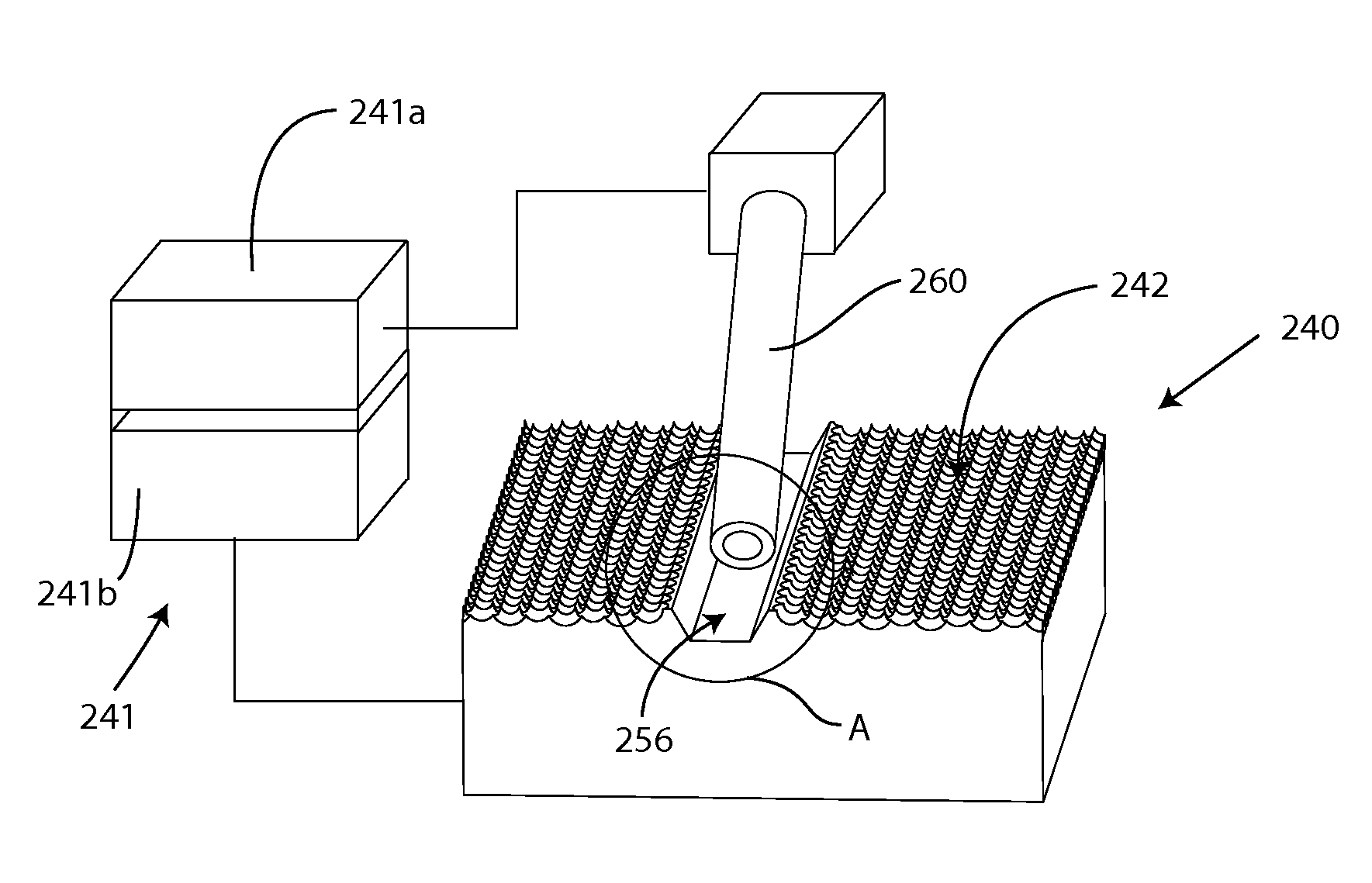
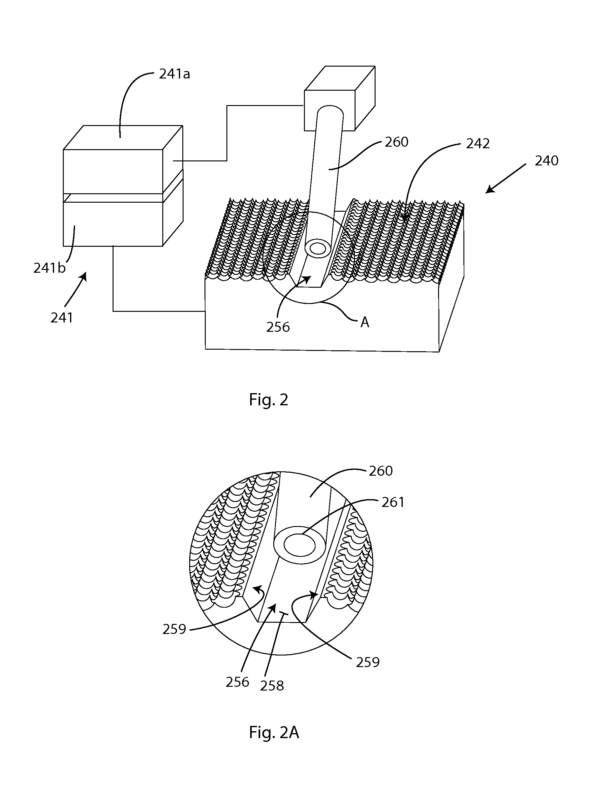
[0044]Inventions disclosed herein relate to applying liquids, slurries and pastes and other similar forms of material that bears a liquid, into grooves (or similar structures) upon a surface of a work piece. The inventions are especially relevant to forming thin metallization elements on photovoltaic absorbers, generally referred to as fingers as generally described in the above referenced PCT application, PCT / US2008 / 002058. This applying liquids, slurries pastes, etc., is referred to generally as treating herein, as well as in the above referenced PCT application. According to inventions disclosed herein, liquid is dispensed and metered in a potentially precisely controlled fashion, under pressure through a fine dispensing capillary tube, which is mechanically guided and aligned by following topography / surface texture on the surface of the work piece. In one embodiment, the work piece is a silicon wafer that has grooves in it for metallization.

[0045]The above referenced PCT applica...


PUM


Abstract

Materials that contain liquid are deposited into grooves upon a surface of a work piece, such as a silicon wafer to form a solar cell. Liquid can be dispensed into work piece paths, such as grooves under pressure through a dispensing tube. The tube mechanically tracks in the groove. The tube may be small and rest at the groove bottom, with the sidewalls providing restraint. Or it may be larger and ride on the top edges of the groove. A tracking feature, such as a protrusion, Non-circular cross-sections, molded-on protrusions and lobes also enhance tracking. The tube may be forced against the groove by spring or magnetic loading. Alignment guides, such as lead-in features may guide the tube into the groove. Restoring features along the path may restore a wayward tube. Many tubes may be used. Many work pieces can be treated in a line or on a drum.

Description

RELATED DOCUMENT[0001]Priority is hereby claimed to U.S. Provisional application Ser. No. 61 / 204,382, entitled DISPENSING LIQUID CONTAINING MATERIAL TO PATTERNED SURFACES USING A CAPILLARY DISPENSING TUBE, in the names of Emanuel M. Sachs, Richard L. Wallace, James F. Bredt and Benjamin F. Polito, filed on Jan. 6, 2009, which is hereby incorporated herein fully by reference.BACKGROUND[0002]Certain processing schemes and architecture are disclosed in Patent Cooperation Treaty Application No: PCT / US2008 / 002058, entitled, SOLAR CELL WITH TEXTURED SURFACES, Filed: Feb. 15, 2008, in the names of Emanuel M. Sachs and James F. Bredt and The Massachusetts Institute of Technology, designating the United States of America, and also claiming priority to two provisional United States applications, No. U.S. 60 / 901,511, filed Feb. 15, 2007, and No. U.S. 61 / 011,933, filed Jan. 23, 2008. All of the PCT application and the two US provisional applications are hereby incorporated fully herein by refer...

Claims


Application Information

Patent Timeline
IPC IPC(8): H01L23/544B65D35/38
CPCH01L31/022425H01L21/6715Y02E10/50
Inventor SACHS, EMANUEL M.WALLACE, RICHARD L.BREDT, JAMES F.POLITO, BENJAMIN F.ERSEN, ALI
Owner 1366 TECH INC
Features
  • R&D
  • Intellectual Property
  • Life Sciences
  • Materials
  • Tech Scout
  • Unparalleled Data Quality
  • Higher Quality Content
  • 60% Fewer Hallucinations
Learn More