
Controllable rectification device and electric motor comprising the same

a rectification device and control technology, applied in the direction of dc-ac conversion without reversal, dynamo-electric motor/converter starter, dc-ac conversion with intermediate conversion, etc., can solve the problems of increasing the cost of the controllable rectification device, the torque and the power limit of the motor, and the low power of the electric motor, etc., to achieve low cost, high power, and low cost

Active Publication Date: 2012-02-16
BYD CO LTD
View PDF6 Cites 5 Cited by
  • Summary
  • Abstract
  • Description
  • Claims
  • Application Information

AI Technical Summary

Benefits of technology

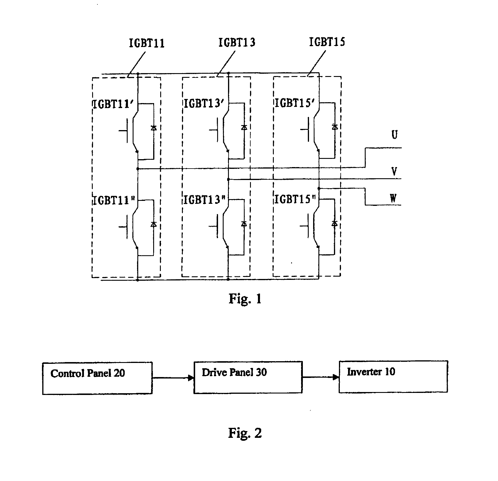
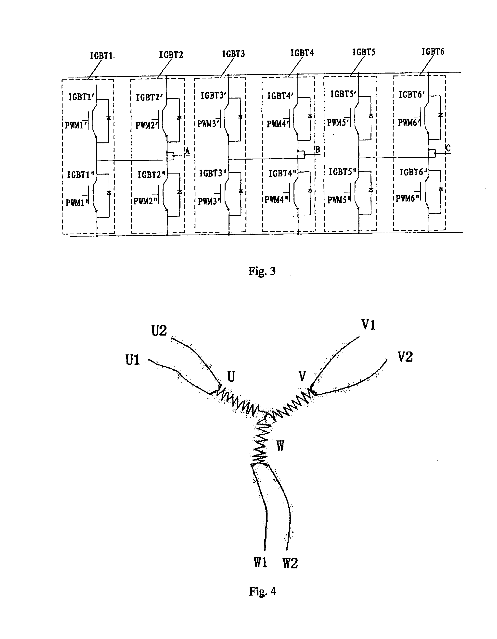
The present invention provides a controllable rectification device with a low cost. The device includes an inverter, a control panel, and a drive panel. The inverter has three switch element groups connected in parallel, each group containing at least two switch elements. The control panel generates a PWM waveform, and the drive panel generates a drive voltage to drive the switch elements separately or simultaneously. This allows for the simultaneous conducting or breaking of the upper and lower bridge-arm switches in the same switch element group. The electric motor comprises three phase windings and the controllable rectification device described above. The device has enhanced current resistant performance, which is better than normally used in the art and reduces the need for expensive high power switch elements. The controllable power range of the device is increased by connecting switch elements with a scale of lower level in parallel, which reduces manufacturing costs while efficiently using available resources.

Problems solved by technology

Currently, hybrid power vehicles generally use the engine and the electric motor as power sources respectively, so that the electric motor may have a low power.
However, for an electric motor with high power, adoption of a normally used low power IGBT in the controllable rectification device may cause some limits of the torque and the power of the motor.
If the low power IGBT is replaced by a high power IGBT, the cost of the controllable rectification device will increase rapidly, because the price of a high power IGBT is normally five times of a low power IGBT.
And the power consumption of the high power IGBT is relatively large which may lead to waste of energy.

Method used


Image

  • Controllable rectification device and electric motor comprising the same
  • Controllable rectification device and electric motor comprising the same
  • Controllable rectification device and electric motor comprising the same

Examples


Embodiment Construction

[0019]Hereinafter embodiments of the invention will be described, the examples of which are shown in the accompanying Figures. Similar labels indicate the same or the similar components, or the components with the same or similar functions. The embodiments below are used for expounding principle and / or theorem of the present invention rather for limitation.

[0020]As shown in FIG. 2, a controllable rectification device may comprise an inverter 10, a control panel 20 and a drive panel 30. The inverter 10 may comprise three switch element groups connected in parallel. Each switch element group may comprise at least two switch elements connected in parallel. Each switch element may comprise an upper bridge-arm switch and a lower bridge-arm switch. The control panel 20 may generate a PWM waveform based on a desired controlling strategy. The drive panel 30 may generate a drive voltage according to the inputted PWM waveform, then to drive the upper bridge-arm switch and the lower bridge-arm...


PUM


Abstract

The present invention discloses a controllable rectification comprising an inverter (10), a control panel (20) and a drive panel (30). The inverter (10) may comprise three switch element groups connected in parallel. Each switch element group may comprise at least two switch elements connected in parallel. Each switch element may comprise an upper bridge-arm switch and a lower bridge-arm. The control panel (20) may generate a PWM waveform. The drive panel (30) may generate a drive voltage according to the PWM waveform to drive the upper bridge-arm switch and the lower bridge-arm switch of each switch element to conduct or break respectively, and to make the upper bridge-arms of the same switch element group to conduct or break simultaneously, and to make the lower bridge-arms of the same switch element group to conduct or break simultaneously. The present invention further discloses an electric motor comprising the same.

Description

CROSS-REFERENCE TO RELATED APPLICATIONS[0001]This application is a continuation of International Application No. PCT / CN2010 / 071295, filed Apr. 20, 2010, which claims priority to and benefit of Chinese Patent Application No. 200910135537.8, filed with the State Intellectual Property Office of P.R. China on Apr. 21, 2009, the contents of which are incorporated by reference herein in their entirety.FIELD OF THE INVENTION[0002]The present invention relates to an electric motor, more particularly, to a controllable rectification device and an electric motor comprising the controllable rectification device.BACKGROUND OF THE INVENTION[0003]Normally, a controllable rectification device for an electric motor comprises an inverter, a control panel and a drive panel. The inverter comprises three switch elements connected in parallel. Each switch element comprises an upper bridge-arm switch and a lower bridge-arm switch. The control panel is used to collect peripheral sample signals, and to gen...

Claims


Application Information

Patent Timeline
Patent Type & Authority Applications(United States)
IPC IPC(8): H02P21/00H02K11/04H02M7/5387
CPCH02M7/493B60L15/025H02P23/0027Y02T10/643H02P21/00Y02T10/64
Inventor JIANG, XIANHONG
Owner BYD CO LTD
Learn More