Floating plane touch input device and method

a technology of touch input device and floating plane, which is applied in the field of floating plane touch input device and method, can solve the problems of touchpad input device, and achieve the effect of avoiding mechanical complexity and improving detection of z-forces

Inactive Publication Date: 2012-02-16
FLOATINGTOUCH
View PDF8 Cites 90 Cited by
  • Summary
  • Abstract
  • Description
  • Claims
  • Application Information

AI Technical Summary

Benefits of technology

[0016]In certain embodiments, a floating touch-plane input device is provided which includes a mounting material that “floats” the touch surface in a manner that accommodates X-Y friction and notably improves detection of Z-forces, while avoiding mechanical complexity.
[0017]In yet other certain embodiments, a force-based touch input device integrates the fluidic mounting and touch sensing functions to motion-enable the touch surface and determine the Z-axis distance changes between the touch surface and the host device while avoiding a detectable position shift of the touch surface, thus diminishing unwanted lateral forces and easing assembly tolerances.
[0018]In certain embodiments, a force-based touch input device employs floating sensing-mounts, or a modular floating sub-assembly of sensing-mounts to replace the existing internal static display mounting with a floating sensing-mount system, and thereby motion-enable the LCD display itself as the touch surface. This eliminates external touch frame and cover glass (as shown in FIG. 1), provides 100% display-image transmission to the user, and avoids extra major component costs or additional bulk, thereby implementing a very thin touch device. The touch surface may commonly be an integral component of the device, such as a display panel or cathode-ray tube, which would result in a touch screen without adding any extra planes or thickness to the device. Absent the display, this method can result in a touchpad input device.
[0019]In certain other embodiments, a force-based touch input device is provided having a multiplicity of sensors arrayed symmetrically or asymmetrically in any locations beneath the touch surface, or above its perimeter, thus enabling higher levels of detection accuracy, greater screen resolution, and multi-touch sensitivity.

Problems solved by technology

Absent the display, this method can result in a touchpad input device.

Method used


Image

  • Floating plane touch input device and method
  • Floating plane touch input device and method
  • Floating plane touch input device and method

Examples


Embodiment Construction

[0031]The following description is presented to enable one of ordinary skill in the art to make and use the invention and is provided in the context of a patent application and its requirements. Various modifications to the preferred embodiments and the generic principles and features described herein will be readily apparent to those skilled in the art. Thus, the present invention is not intended to be limited to the embodiments shown, but is to be accorded the widest scope consistent with the principles and features described herein.

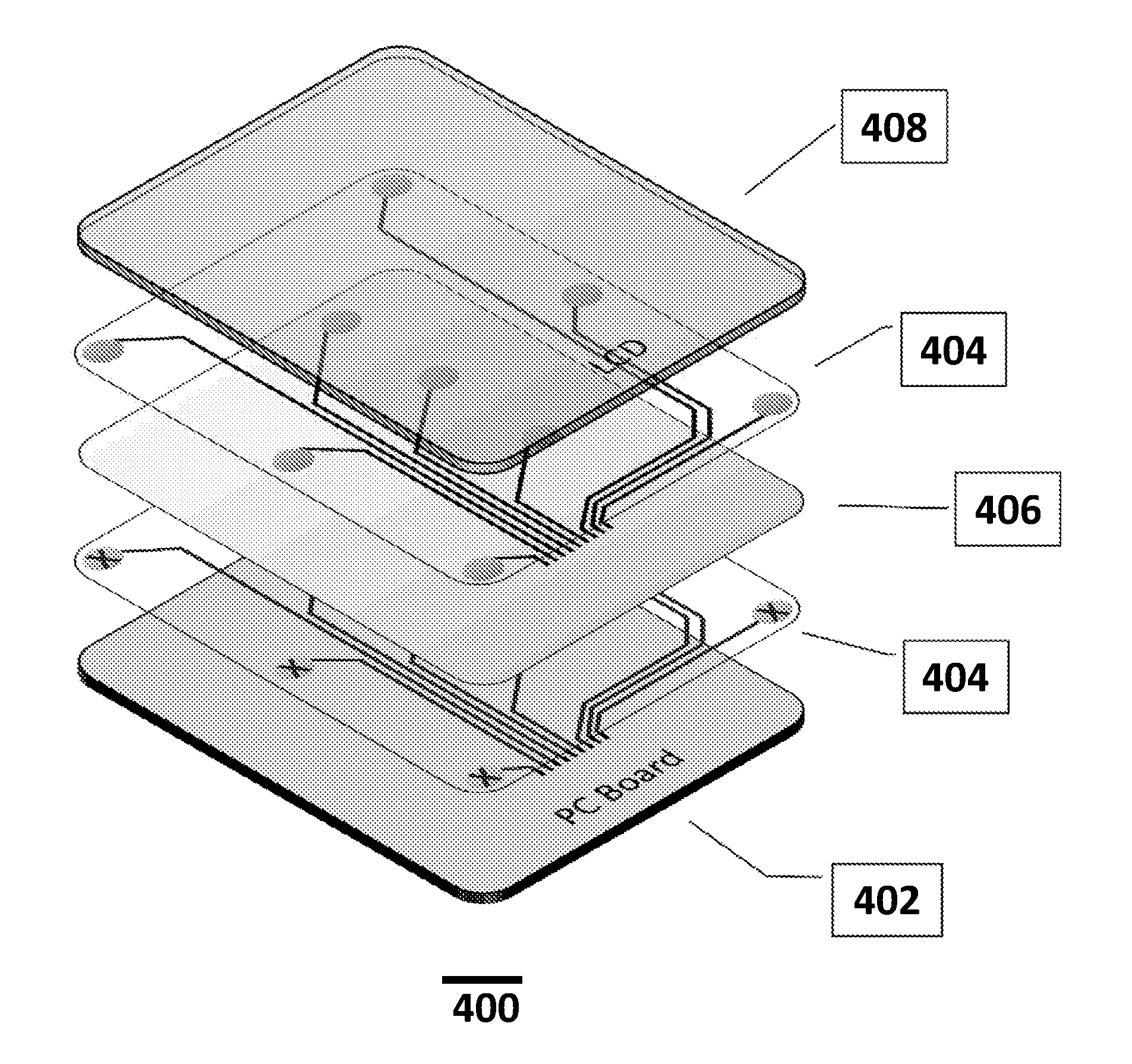
[0032]A system and method in accordance with the present invention specifies an integrated, flexible “sensing-suspension” to separate, affix and motion-enable (collectively, to “float”) a touch surface relative to its host device, all representing the “suspension” function. When the user touches the touch surface, an integrated sensing framework (representing the “sensing” function) detects and measures displacement changes in the touch surface, while ...


PUM


Abstract

A touch input device and method for manufacturing a touch input device are described. Each embodiment includes a touch surface, a mounting fixture, a sensing-suspension system, and a locating system. The touch surface may be an integral component of a host system, such as a display, which would result in a touch screen, or a touchpad input device. The touch surface is a floating plane, where the suspension positions, attaches and motion-enables the touch surface within the host system, and where the force exerted on the touch surface causes displacement of the touch surface, which motion is interpreted to calculate a touch location.

Description

CROSS-REFERENCE TO RELATED APPLICATIONS[0001]This application claims the benefit of U.S. Provisional Application No. 61 / 374,148, filed on Aug. 16, 2010, entitled “FLOATING-PLANE TOUCH INPUT DEVICE AND METHOD,” which is incorporated herein by reference in its entirety.FIELD OF THE INVENTION[0002]The present invention generally relates to electronic devices and methods and more particularly to a method and system for providing touch input to an electronic device.BACKGROUND[0003]Touch screens are finding increasing use for providing input to electronic devices. Most current touch systems resort to an overlay film using capacitive or resistive technology. These films use intersecting rows and columns of wires to locate a touch by its physical position, making it costly to maintain fine resolution on ever-larger screen dimensions. Touch screens produced this way have limitations, including a clean-room overlay process that adds cost and reduces the transmissivity of displays.[0004]Force-...

Claims


Application Information

Patent Timeline
Patent Type & Authority Applications(United States)
IPC IPC(8): G06F3/041H05K7/00
CPCG06F3/04845G06F3/0484G06F2203/04806G06F3/04883G06F3/0414G06F3/04144G06F2203/04105
Inventor BROWN, DANIELMALINIAK, KRYSTYNACAPONE, FRANK N.
Owner FLOATINGTOUCH
Why Eureka
Try Eureka