Wide angle hologram device illuminated with a near field source and method for manufacturing same

Active Publication Date: 2012-02-16
CIAUDELLI PRODN
View PDF8 Cites 18 Cited by
  • Summary
  • Abstract
  • Description
  • Claims
  • Application Information

AI Technical Summary

Benefits of technology

[0017]In yet another embodiment of the present invention, a two step low cost method of making a wide ang

Problems solved by technology

However a compact display is not possible due to reconstruction involving a laser positioned at a distance from the hologram.
In addition, the Nicholson device also sacrifices some vertical para

Method used


Image

  • Wide angle hologram device illuminated with a near field source and method for manufacturing same
  • Wide angle hologram device illuminated with a near field source and method for manufacturing same
  • Wide angle hologram device illuminated with a near field source and method for manufacturing same

Examples


Embodiment Construction

[0025]It is to be understood that the figures and descriptions of the present invention have been simplified to illustrate elements that are relevant for a clear understanding of the present invention, while eliminating, for purposes of clarity, many other elements which are conventional in this art. Those of ordinary skill in the art will recognize that other elements are desirable for implementing the present invention. However, because such elements are well known in the art, and because they do not facilitate a better understanding of the present invention, a discussion of such elements is not provided herein.

[0026]The present invention will now be described in detail on the basis of exemplary embodiments.

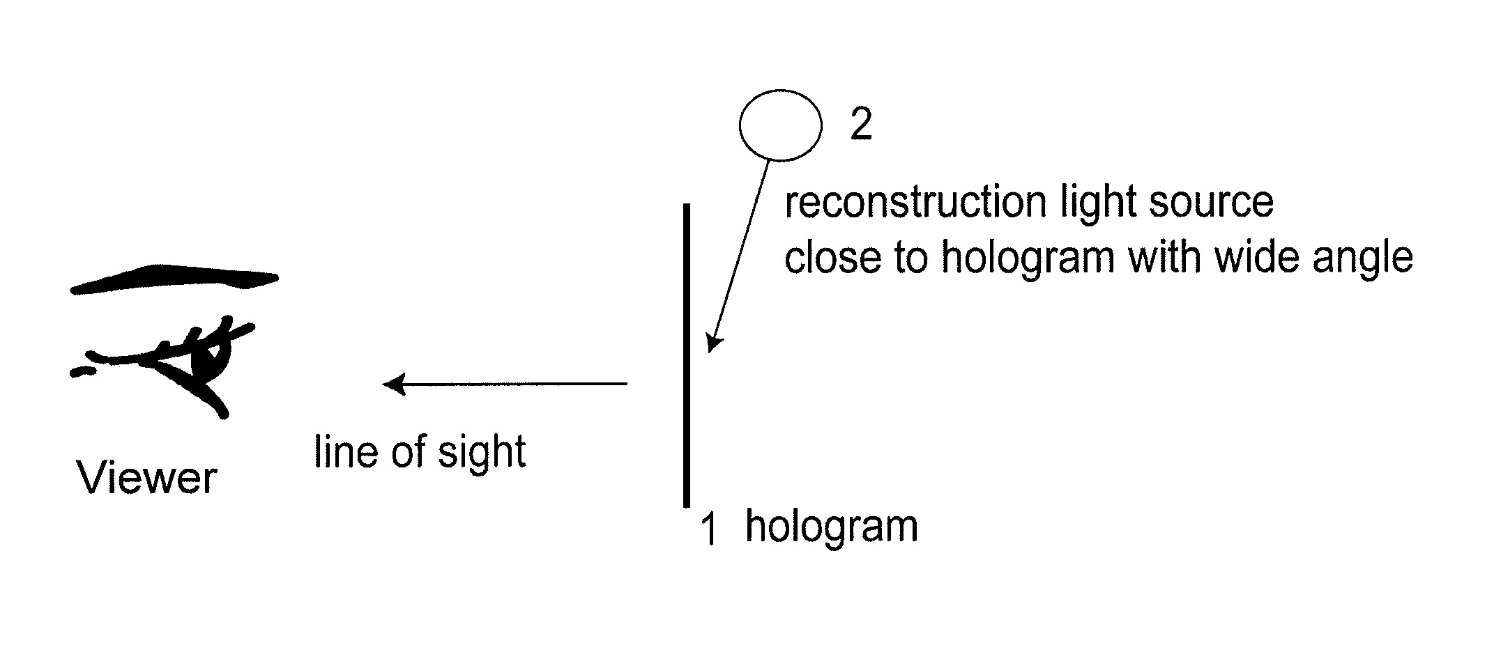
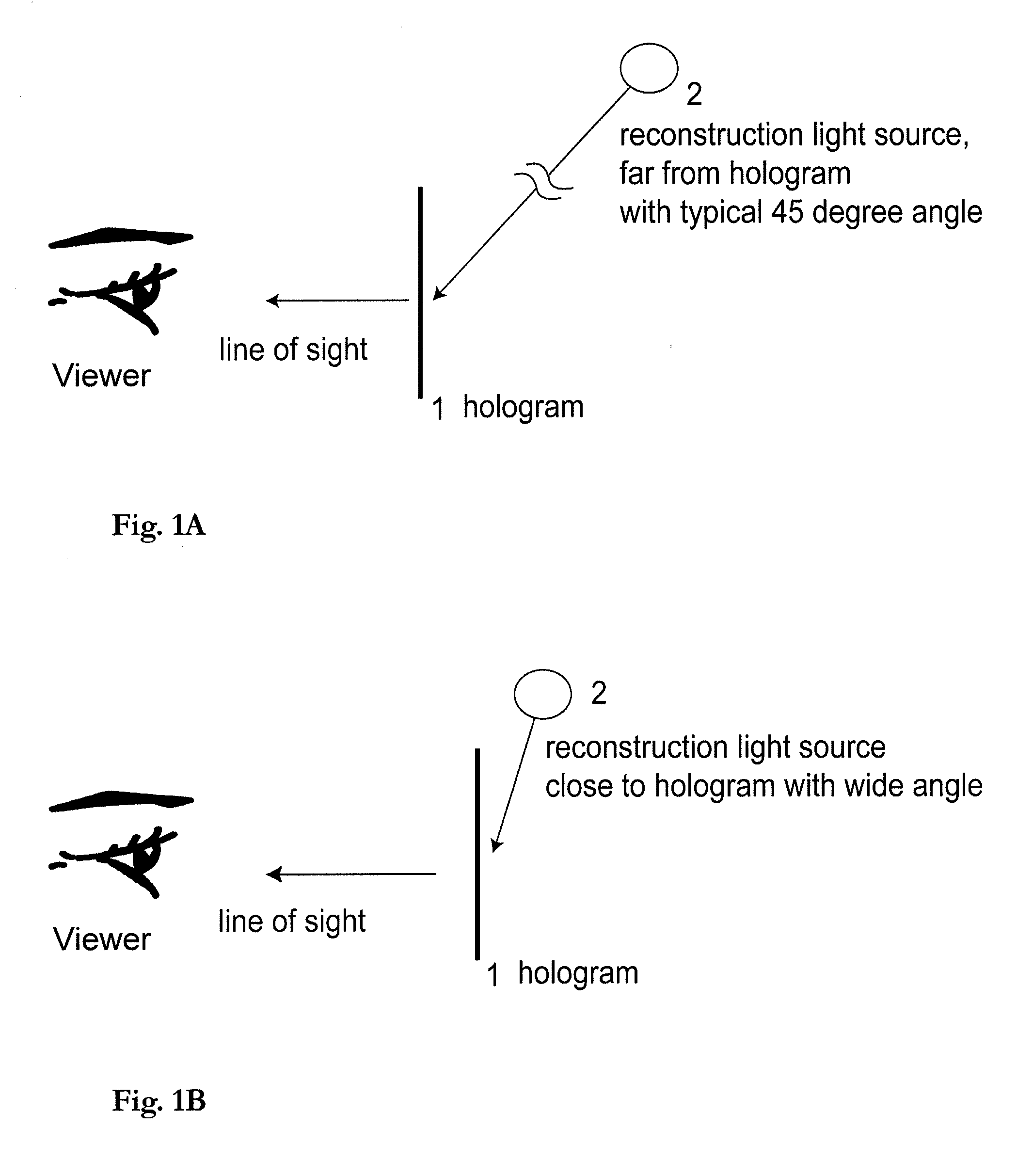
[0027]For image reconstruction, the present hologram invention uses a near field light source angled greater than 75 degrees in relation to the perpendicular of the film plane. In the hologram embodiment shown in FIGS. 4A and 4B, for use as an advertising display, the depth of ...


PUM


Abstract

A method of manufacturing a master for producing a hologram device is provided. The holographic image reconstructs when the photosensitive film of the hologram device is struck by a beam of light from a wide angle being defined relative to a perpendicular line to a surface of the photosensitive film.

Description

BACKGROUND OF THE INVENTION[0001]1. Field of the Invention[0002]This invention relates to holograms and particularly a wide angle hologram device with an image that is reproduced from a near field illuminating source, and method of manufacturing same.[0003]2. Description of Related Art[0004]A hologram or hologram device is a device that includes a photosensitive film containing a recordation of an object. As is well-known, holograms are recorded with coherent light with a reference beam that strikes the photosensitive film directly and an object beam which strikes that object to be recorded and then strikes the film. The angles of these beams in relation to the plane of the film determines how the recorded image will be reproduced from the finished hologram, a process known as reconstruction. The image becomes visible when the hologram is illuminated by an appropriate light source from the same angle of either the reference beam or the object beam that was used during the recording ...

Claims


Application Information

Patent Timeline
IPC IPC(8): G03H1/20G03H1/22
CPCG03H1/20G03H1/22G03H1/2286G03H2001/207G03H2001/2223G03H2001/2231G03H2001/2234G03H2222/42G03H2222/54G03H2227/06G03H2001/2278G03H2210/20G03H2210/30
Inventor CIAUDELLI, JOSEPH J.CVETKOVICH, THOMAS
Owner CIAUDELLI PRODN
Why Eureka
Try Eureka