Electric connector

Inactive Publication Date: 2012-02-16
ALINER INDS
View PDF3 Cites 15 Cited by
  • Summary
  • Abstract
  • Description
  • Claims
  • Application Information

AI Technical Summary

Benefits of technology

[0012]The primary objective of the present invention is to provide an electric connector including a socket member or receptacle having an increased contacting area with the in-plug electric wire or cable for firmly and stably coupling or connecting the

Problems solved by technology

However, the receptacle includes a tilted or inclined or tapered structure that may be engaged with the in-plug electric wires or cables in a point or line contact, i.e., the in-plug electric wires or cables are only in line contact with the receptacle such that the contacting area between the in-plug electric wire or cable and the receptacle is small and such that the electric contact between the in-plug electric wire or cable and the receptacle will become fail.
However, the receptacle contact includes a tilted or inclined or tapered structure that may be engaged with the in-plug electric wires or cables in a point or line contact, i.e., the in-plug electric wires or cables are only in line contact with the receptacle contact s

Method used


Image

  • Electric connector
  • Electric connector
  • Electric connector

Examples


Embodiment Construction

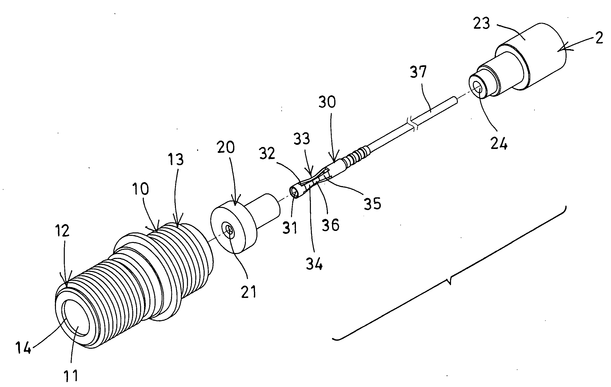
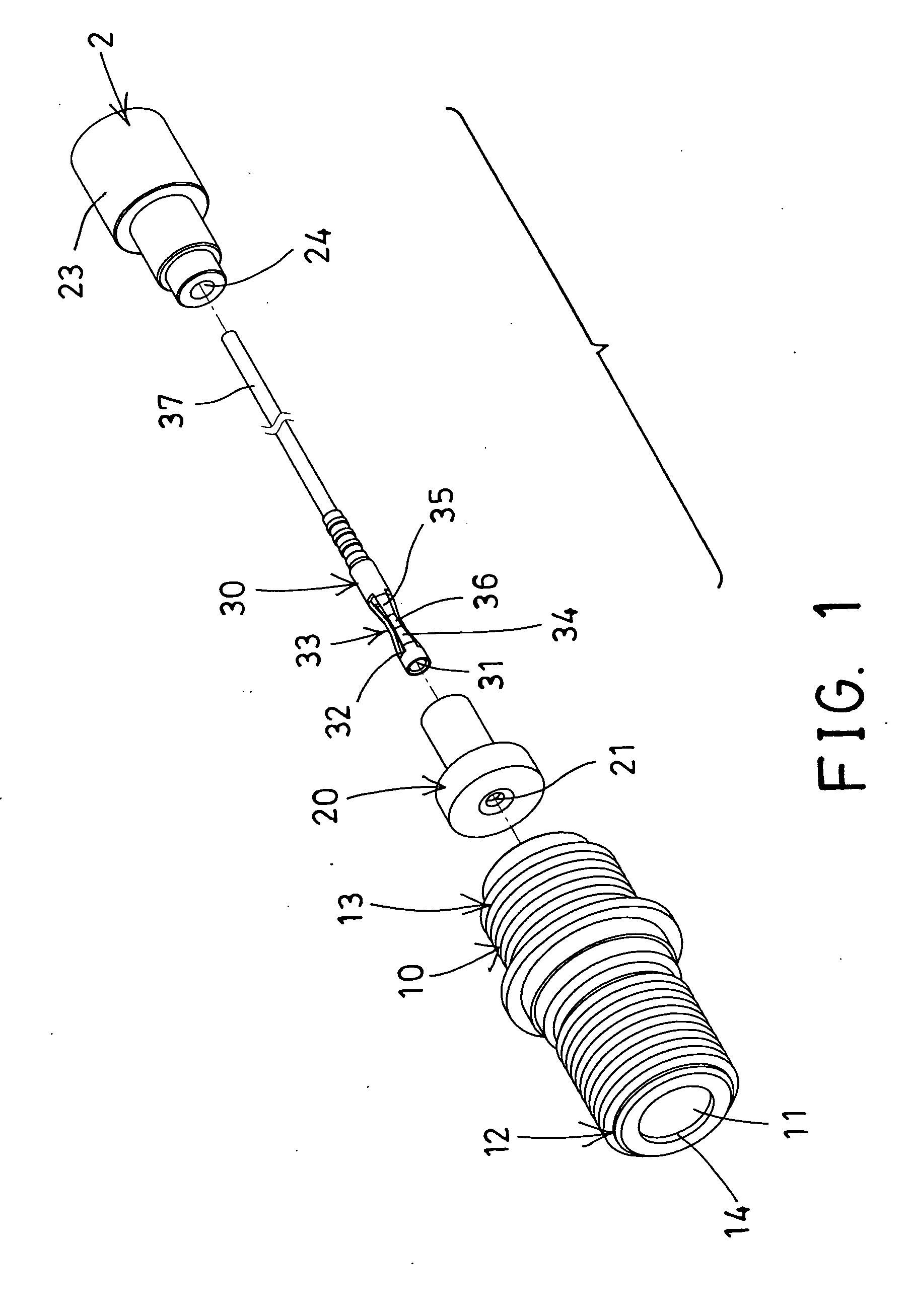
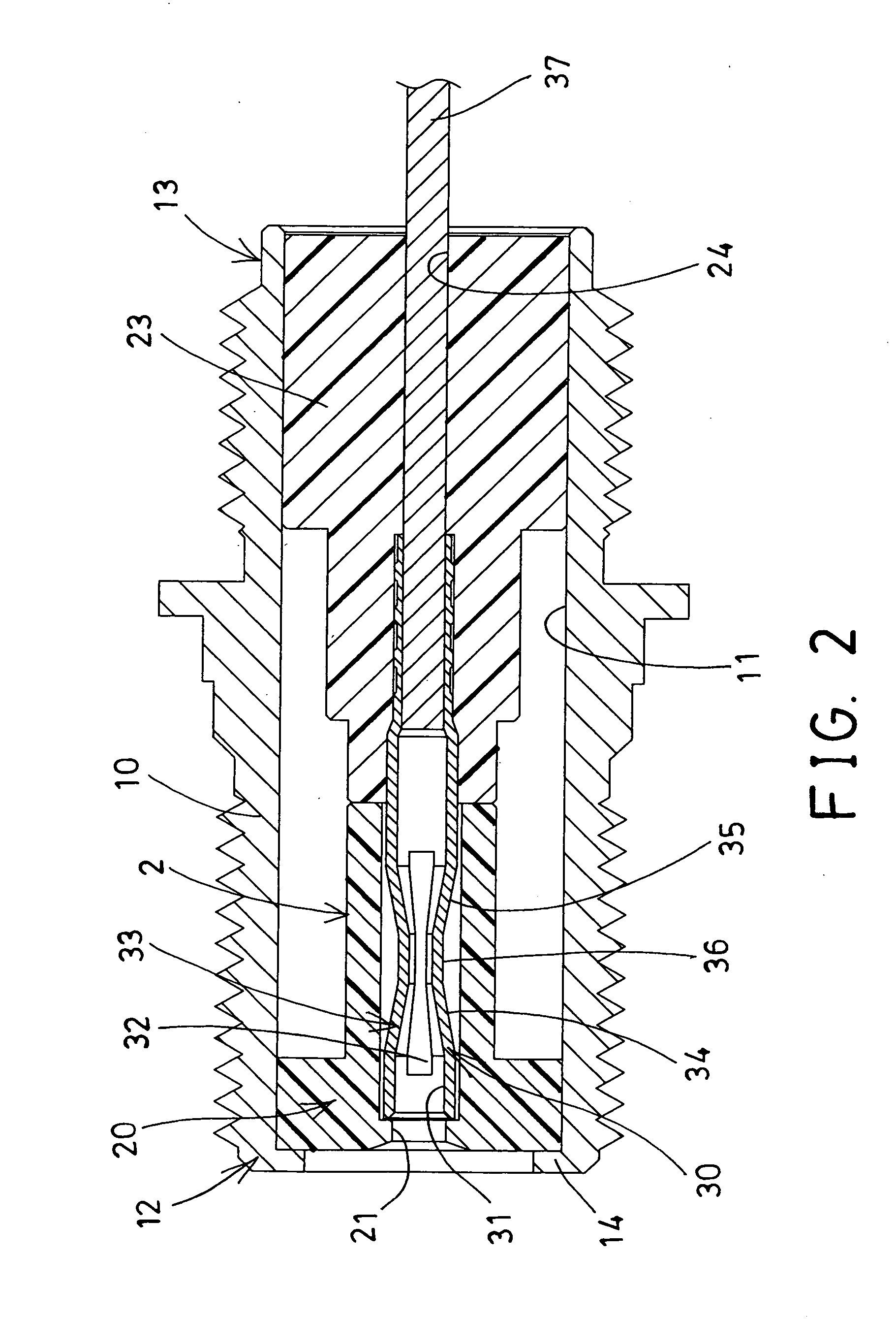
[0024]Referring to the drawings, and initially to FIGS. 1-2, an electric connector in accordance with the present invention comprises an outer adaptor shell 10 including a bore or chamber 11 formed therein, an insulating device 2 including a first insulating member 20 disposed or engaged into the chamber 11 and at one end 12 of the adaptor shell 10 and having an orifice or bore 21 formed in the first insulating member 20, and including a second insulating member 23 also disposed or engaged into the chamber 11 but at the other end 13 of the adaptor shell 10 and including an aperture or bore 24 formed in the second insulating member 23.

[0025]It is preferable, but not necessarily that the adaptor shell 10 includes an inner peripheral flange 14 extended radially and inwardly from the one end 12 thereof for engaging with the first insulating member 20 and for stably or solidly anchoring or positioning or retaining or confining the first insulating member 20 in the one end 12 of the adapt...


PUM


Abstract

An electric connector includes an insulating device disposed into a chamber of an adaptor shell, and a receptacle engaged into the bore of the insulating device and having a compartment for receiving an electric cable and having one or more slots for forming or defining one or more blades, the blades each include two side segments and an intermediate segment disposed between the side segments and located in the compartment of the receptacle for engaging with the electric cable and for increasing a contacting area between the blade and the electric cable and for firmly coupling the in-plug electric cable to the receptacle and for decreasing the impedance between the in-plug electric cable and the receptacle and for reducing the return loss of the electric connector.

Description

BACKGROUND OF THE INVENTION[0001]1. Field of the Invention[0002]The present invention relates to an electric connector, and more particularly to an electric connector including a socket member or receptacle having an increased contacting area with the in-plug electric wire or cable for firmly and stably coupling or connecting the in-plug electric wire or cable to the receptacle of the electric connector and for decreasing the impedance between the in-plug electric wire or cable and the receptacle of the electric connector and for reducing the return loss of the electric connector.[0003]2. Description of the Prior Art[0004]Typical electric connectors comprise one or more socket members for receiving or engaging with the in-plug electric wires or cables and for electrically coupling or connecting the in-plug electric wire or cable to the socket member.[0005]For example, U.S. Pat. No. 4,206,963 to English et al. discloses one of the typical connector filtered adapter assemblies compris...

Claims


Application Information

Patent Timeline
IPC IPC(8): H01R9/05
CPCH01R9/05H01R13/502H01R13/111
Inventor SHIH, TING CHUWU, MENG CHIEH
Owner ALINER INDS
Why Eureka
Try Eureka