
External fixator system

a fixator system and fixation plate technology, applied in the field of manipulating the position of two or more fixation plates of an external fixator system, to achieve the effects of convenient patient access, increased patient compliance, and compact structur

Active Publication Date: 2012-02-16
STRYKER EURO OPERATIONS HLDG LLC
View PDF3 Cites 76 Cited by
  • Summary
  • Abstract
  • Description
  • Claims
  • Application Information

AI Technical Summary

Benefits of technology

[0008]The actuation unit preferably provides a gradual telescopic motion due to the arrangement of a feedback unit which is advantageous for the user. Due to the fixed connection with the fixation plate, it is possible to provide a very compact structure as the actuation unit can be arranged partly within the plate.
[0009]Preferably the actuation unit comprises a socket which is adapted to receive a tool to be actuated, whereby the socket is oriented such that it extends in or almost in direction of the strut and / or such that it extends perpendicular to a front surface of the fixation plate. This orientation has the advantage that the user gains very ergonomic access to actuate the actuation element. Hence this mechanism allows the effective length of the adjustable length strut to be adjusted from the top which allows easier patient access. This increases patient compliance one of the significant challenges in deformity correction with an external fixator system.
[0012]The outer sleeve extends preferably into an opening which is arranged in the fixation plate, wherein the opening and the outer sleeve have a corresponding shape such that a relative rotation between the fixation plates is prevented.
[0018]In another embodiment of this first aspect of the present invention, the through-hole of one of the at least two fixation plates and the outer sleeve of the actuation unit include corresponding outer surfaces having at least two different diameters such that relative rotation between the actuation unit and the one of the at least two fixation plates is prevented.

Problems solved by technology

This increases patient compliance one of the significant challenges in deformity correction with an external fixator system.

Method used


Image

  • External fixator system
  • External fixator system
  • External fixator system

Examples


Embodiment Construction

[0029]As used herein, when referring to the drill guides of the present invention, the term “proximal” means closer to the surgeon or in a direction toward the surgeon and the term “distal” means more distant from the surgeon or in a direction away from the surgeon. The term “anterior” means towards the front part of the body or the face and the term “posterior” means towards the back of the body. The term “medial” means toward the midline of the body and the term “lateral” means away from the midline of the body.

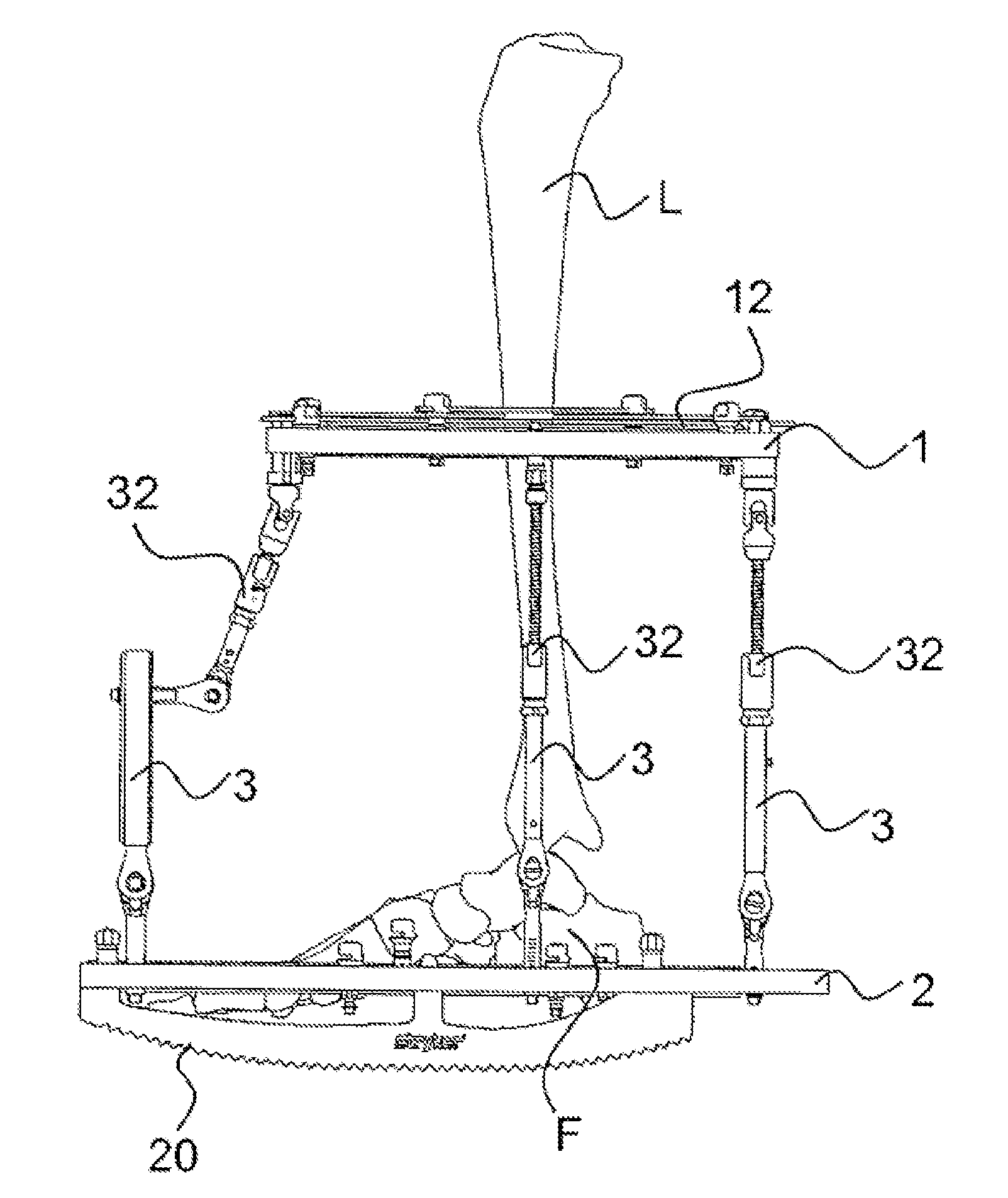
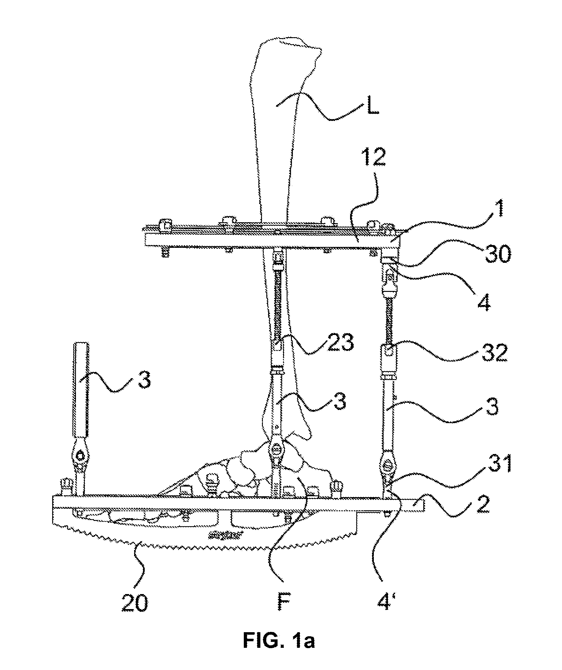
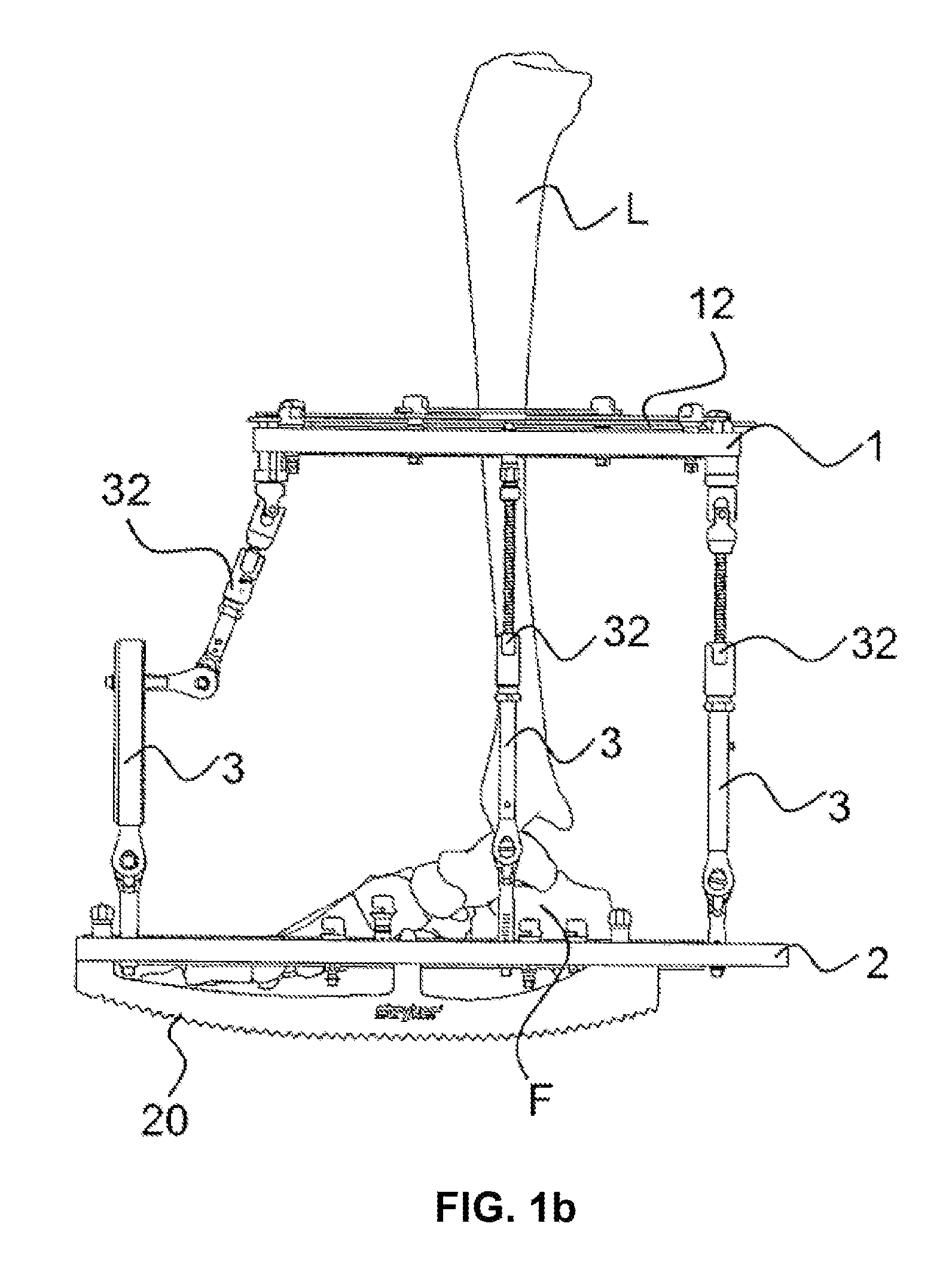
[0030]Referring to FIGS. 1-6, there is shown an embodiment of an external fixator system of the present invention. As shown in those figures, the external fixator system includes first and second fixation plates 1, 2 coupled to first and second bone segments L, F respectively, a plurality of adjustable length struts 3, at least one actuation unit 4, and a plurality of clamping units 4′.

[0031]FIGS. 1a-c show an exemplary embodiment of an external fixator system. The external...


PUM


Abstract

An external fixator system comprising at least two fixation plates which are arranged at a distance to each another, at least one adjustable length having a first end region and a second end region which are in connection with the fixation plates and at least one actuation unit to adjust the length of the strut in order to adjust the distance and / or orientation between the fixation plates. The actuation unit is in a fixed connection with at least one of the fixation plates as well as with at least one of the end regions of the respective strut in order to connect the strut with the fixation plate. The actuation unit comprises a feedback unit which provides the user with a feedback concerning the degree of the actuation.

Description

CROSS-REFERENCE TO RELATED APPLICATIONS[0001]This application is related to European Application No. 10 172 523.2 filed Aug. 11, 2010, and European Application No. 11 176 512.9 filed on Aug. 4, 2011, the disclosures of which are hereby incorporated herein by reference.FIELD OF THE INVENTION[0002]The present invention relates to manipulating the position of two or more fixation plates of an external fixator system, and more particularly, to manipulating the position of two or more fixation plates with respect to one another by actuating an adjustment member or actuation unit located in a user-friendly position wherein the actuation of the adjustment member also provides feedback to the user.BACKGROUND OF THE INVENTION[0003]Many different types of bone deformities can be corrected using external fixation systems to perform the distraction osteogenesis process. For example, an Ilizarov device or similar external fixation system may be used. Such systems generally use rings also designa...

Claims


Application Information

Patent Timeline
IPC IPC(8): A61B17/00
CPCA61B17/62A61B17/60A61B17/8875A61B17/66
Inventor SINGH, MANOJ KUMARCROZET, YVES STEPHANEBURGHERR, VINZENZ ANDREAS
Owner STRYKER EURO OPERATIONS HLDG LLC
Learn More