Mechanical actuator

Active Publication Date: 2012-02-23
NOOK IND LLC
View PDF10 Cites 43 Cited by
  • Summary
  • Abstract
  • Description
  • Claims
  • Application Information

AI Technical Summary

Problems solved by technology

Roller screws can carry heavy loads for thousands of hours in demanding and continuous-duty conditions.
The exemplary application requirements and others can cause several inherent problems in operation.
Roller screw actuators are susceptible to high-energy demand, wear of individual parts, excess debris, and actuator failure.
Many of the failure modes of mechanical and electromechanical actuators are caused by insufficient or failed lubrication, and an inability to manage wear debris in a programmed or systematic manner.
Other drawbacks of roller screw actuators exist caused directly or in part by limitations of conventional lubrication systems.

Method used


Image

  • Mechanical actuator
  • Mechanical actuator
  • Mechanical actuator

Examples


Embodiment Construction

[0042]This Detailed Description of the Invention merely describes embodiments of the invention and is not intended to limit the scope of the claims in any way. Indeed, the invention as claimed is broader than and unlimited by the preferred embodiments, and the terms used in the claims have their full ordinary meaning.

[0043]Electromechanical actuators are typically not able to run at the same duty cycle and lifetime as hydraulic cylinders. The inventive actuator has an integrated system to allow the electromechanical actuator to achieve performance levels typical of a hydraulic cylinder and control system, as evaluated from a performance, life, precision, duty cycle, and speed standpoint.

Discussion of Actuator

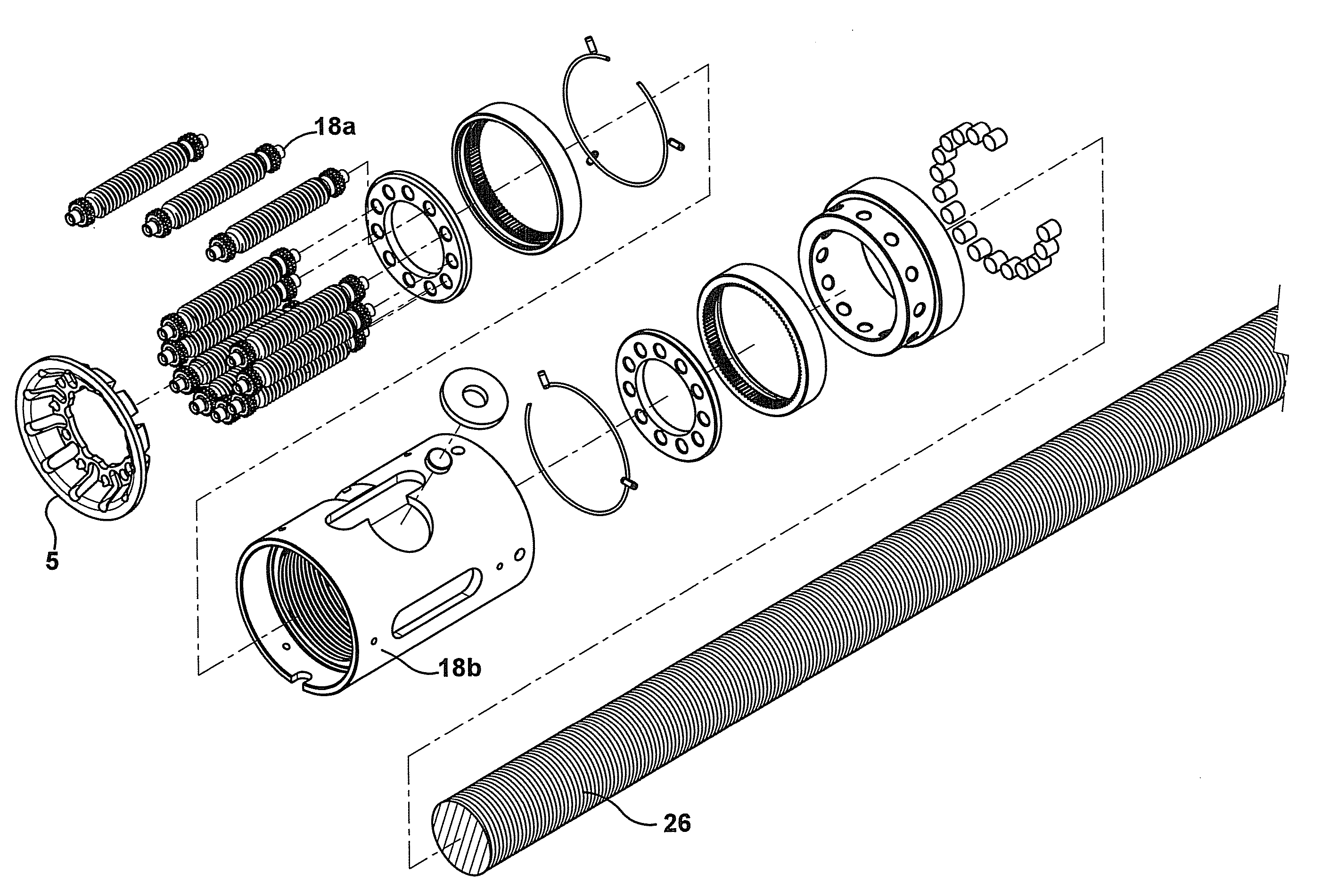
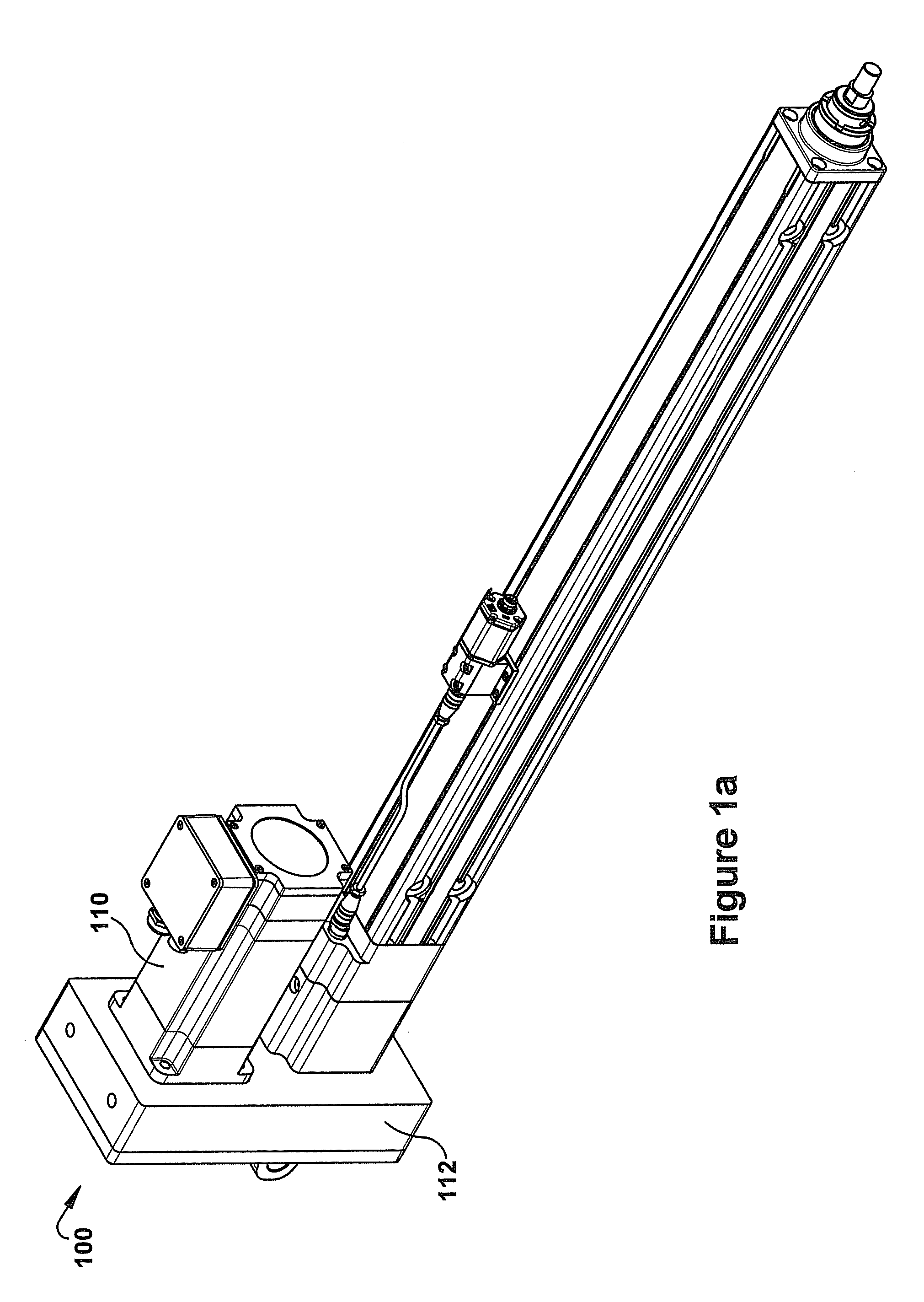
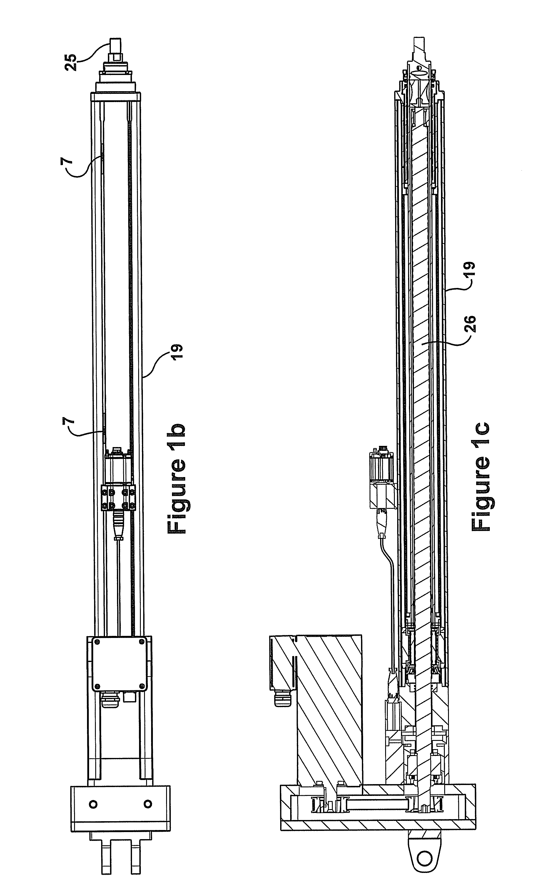
[0044]The inventive actuator is structured in an interactive arrangement of several integrated systems. The systems may be arranged to be dependable of one another and synergistically work together for optimum performance of the actuator.

[0045]A mechanical actuator includes two ...


PUM


Abstract

A mechanical actuator for translating rotational motion to linear motion. The actuator includes a motor, a screw assembly, a bearing assembly, and first and second lubrication systems. The screw assembly includes a housing, a threaded screw shaft disposed within the housing, a nut assembly, and an extension tube. The threaded screw shaft is rotatable by the motor. The nut assembly is arranged to move in either direction along a longitudinal axis of the threaded screw shaft when the threaded screw shaft is in rotational motion, thereby moving the extension tube between an extended position and a retracted position. The bearing assembly is arranged to provide support to at least a portion of a length of the threaded screw shaft. A pathway of the first lubrication system is remote and isolated from a pathway of the second lubrication system.

Description

CROSS-REFERENCE TO RELATED APPLICATION[0001]This application claims the benefit of U.S. Provisional Patent Application Ser. No. 61 / 375,432, entitled MECHANICAL ACTUATOR and filed Aug. 20, 2010, the entire disclosure of which is incorporated herein by reference, to the extent that it is not conflicting with the present application.FIELD OF THE INVENTION[0002]The present invention relates to a mechanical actuator having a synergistic design permitting multiple integrated systems for efficient and improved performance.BACKGROUND OF THE INVENTION[0003]Mechanical actuators of various construction and design, such as linear actuators, are well-known in the art. A linear actuator generally transforms rotational motion into linear motion and typically includes a threaded elongated screw or nut component powered by a rotational motion source. The screw or nut movement is converted by a piston or other means to produce linear back and forth cyclic movement of an output member, such as for exa...

Claims


Application Information

Patent Timeline
IPC IPC(8): F16H57/04F16H25/12
CPCF16H25/2252F16H57/0401F16H57/0464Y10T74/18744F16H57/0497F16H25/20F16H57/0434F16H57/0471
Inventor JACOB, WILLIAM VINCENTKARMANSKY, RAYMOND A.DANIHER, NATHAN RYAN
Owner NOOK IND LLC
Why Eureka
Try Eureka