Outdoor photovoltaic generator

a photovoltaic generator and outdoor technology, applied in photovoltaics, solar heat collectors for particular environments, heat collector mounting/support, etc., can solve the problems of reducing the electrical resistance of shaded cells, reducing the output, and overall less favorable orientation of pv modules to the sun

Inactive Publication Date: 2012-02-23
ADENSIS
View PDF9 Cites 7 Cited by
  • Summary
  • Abstract
  • Description
  • Claims
  • Application Information

AI Technical Summary

Benefits of technology

[0019]With the background knowledge of the above-described, new technology for photovoltaic cells, this intentional misalignment of the outdoor system no longer has the effect of a dramatic output reduction during the periods of sun position when the inclination and misalignment to the south result in shading of a part of the PV module.

Problems solved by technology

Rotating the rows out of the east-west axis (corresponding to an orientation of the PV modules out of the south direction) would lead to a reduced output, which results firstly from the overall less favorable orientation of the PV modules with respect to the sun.
When classic photovoltaic modules are used, with a matrix having a plurality of series-connected photovoltaic cells arranged in a serpentine pattern on the module surface, this shading has the disadvantageous effect that the darkening increases the electrical resistance of the shaded cells.
This effect can lead to a cessation of the photovoltaically generated DC current.
Thus, even a single leaf that completely covers one of the photovoltaic cells results in dropout of the entire PV module.

Method used


Image

  • Outdoor photovoltaic generator
  • Outdoor photovoltaic generator
  • Outdoor photovoltaic generator

Examples


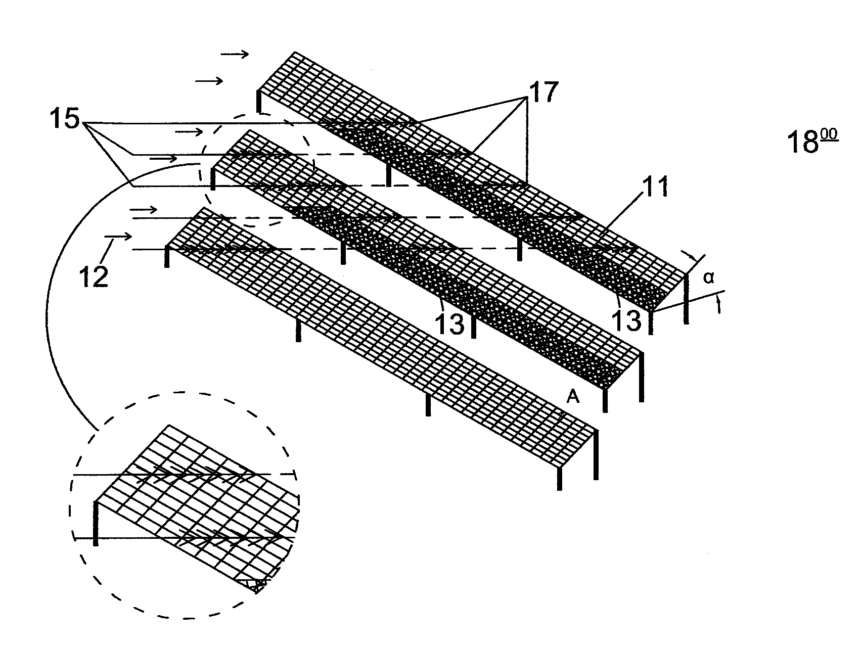
Embodiment Construction

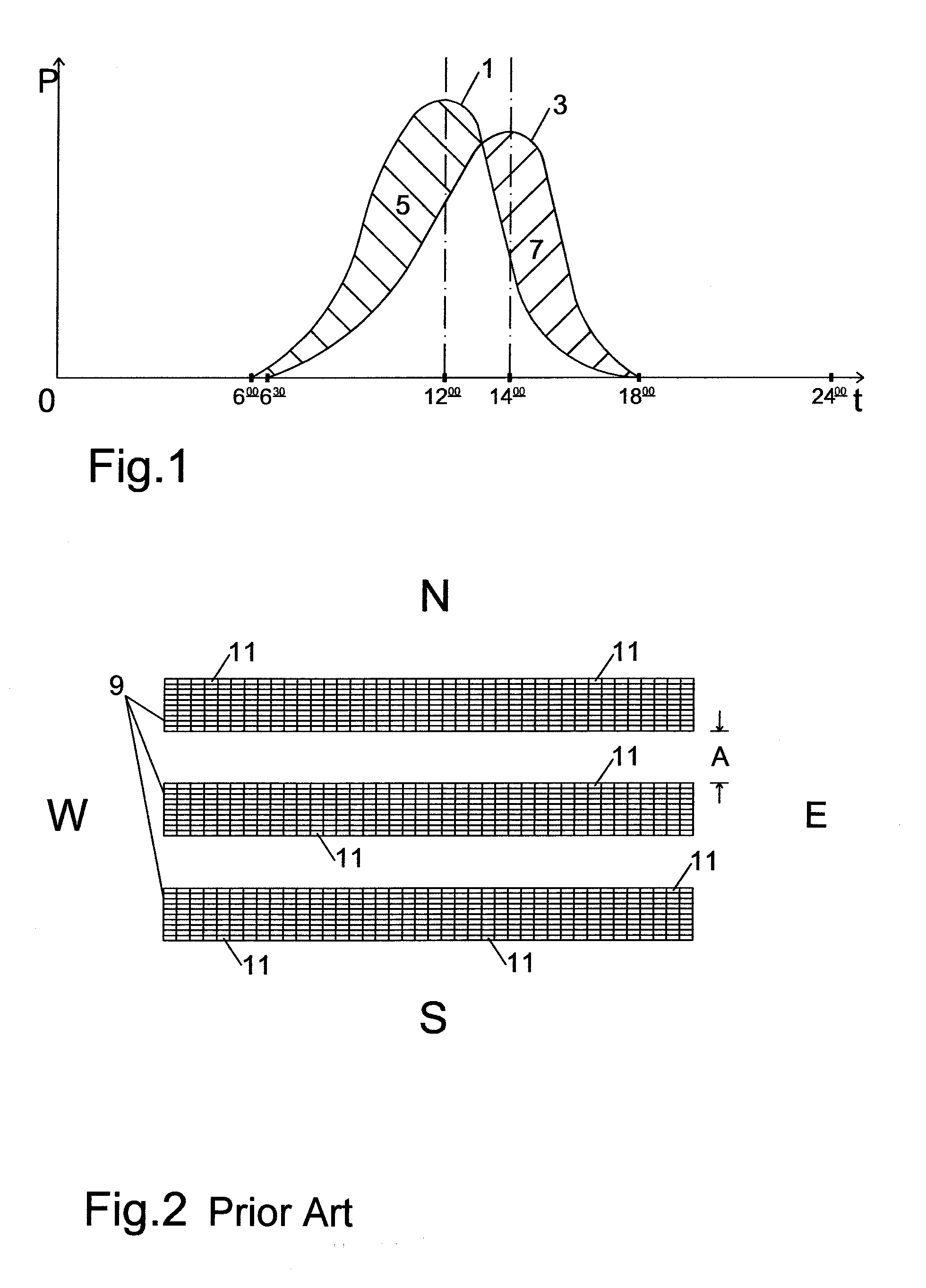
[0030]In FIG. 1, which will be used to describe the a desired effect in detail, the photovoltaically generated energy E is plotted over the time of day t. For the sake of simplicity, a time period between 6:00 A.M. and 6:00 P.M. is considered here. At 12:00, the sun is at its highest point, and the PV generator is delivering its maximum output. The behavior of the output or delivered energy E is plotted as a thin line 1. To the left and right of the maximum, the curve has a largely symmetrical shape according to a Gaussian distribution.

[0031]A rotation of the PV generator by, e.g., 30° toward the northeast has the effect that, in the case of a low sun position at 6:00 A.M., at first only the back of the PV modules is illuminated, and only later at, e.g., approximately 6:30 A.M., does the top of the PV modules receive sufficient solar energy to start feeding power to the grid. This effect is illustrated in the path of the curve along the thick line 3, in that the power feed starts la...


PUM


Abstract

An outdoor photovoltaic generator is provided that has a plurality of straight, parallel rows of rectangular photovoltaic modules that are located on a substructure, each of which comprises a plurality of photovoltaic cells. The photovoltaic cells are arranged on each photovoltaic module such that, in the event of a shading extending parallel to an edge of the photovoltaic module, the energy conversion and transport function of the remaining, unshaded photovoltaic cells or photovoltaic cell regions of the photovoltaic module is maintained. The substructure provides equal inclination of the photovoltaic modules with respect to south. The rows with respect to the east-west direction are installed rotated at an angle between 10° and 40° toward the northeast or toward the northwest. In exchange for acceptance of a reduction in the total output of photovoltaically produced energy as seen over the course of the day, the arrangement permits a displacement of the maximum output to a time of day other than 12:00 noon.

Description

[0001]This nonprovisional application claims priority under 35 U.S.C. §119(a) to German Patent Application No. DE 10 2010 035 000.1, which was filed in Germany on Aug. 20, 2010, and is herein incorporated by reference.BACKGROUND OF THE INVENTION[0002]1. Field of the Invention[0003]The invention relates to an outdoor photovoltaic generator with a plurality of straight, parallel rows of rectangular photovoltaic modules that are located in a fixed manner on a stationary substructure, and each of which comprises a single string or multiple strings of series-connected photovoltaic cells, the ends of which form a first and a second output pole of the photovoltaic module.[0004]The invention additionally relates to outdoor photovoltaic generators of the above-mentioned type in which the rows of rectangular photovoltaic modules have gaps, so that each row includes groups of photovoltaic modules.[0005]2. Description of the Background Art[0006]An outdoor generator can be understood to be a sys...

Claims


Application Information

Patent Timeline
Patent Type & Authority Applications(United States)
IPC IPC(8): H01L31/042
CPCF24J2/523F24J2002/0084H01L31/042H01L31/0465Y02E10/47H02S20/00Y02E10/50H01L31/02021H02S10/00H02S20/10F24S2020/16F24S25/10
Inventor BECK, BERNHARD
Owner ADENSIS
Why Eureka
Try Eureka