Fabricating and operating a memory array having a multi-level cell region and a single-level cell region

a memory array and multi-level cell technology, applied in the field of non-volatile memory, can solve the problems of program disturbance, mlc block reliability is greater, and the endurance may be a more significant problem, so as to achieve high endurance and high reliability. the effect of sl

Active Publication Date: 2010-09-30
SANDISK TECH LLC
View PDF17 Cites 63 Cited by
  • Summary
  • Abstract
  • Description
  • Claims
  • Application Information

AI Technical Summary

Benefits of technology

[0011]The present invention addresses the above and other issues by providing a non-volatile storage system, a method for forming a non-volatile storage system, and a method for operating a non-volatile storage system which provide high endurance for SLC blocks and high reliability for MLC blocks.

Problems solved by technology

Therefore, endurance may be a more significant problem for SLC blocks than for MLC blocks.
On the other hand, because the MLC blocks have more states than SLC blocks, the states are packed in more closely, which leads to greater reliability problem with MLC blocks.
An example of a reliability problem is program disturb, which may be experienced during programming due to the proximity of the non-volatile storage elements to one another.
Program disturb occurs when the threshold voltage of a previously-programmed non-volatile storage element is shifted due to subsequent programming of other non-volatile storage elements.
Because MLC blocks have more states and, therefore, have less separation between the threshold voltage of one state and the next, program disturb is a greater problem for MLC blocks then for SLC blocks.
However, it can be difficult to form SLC blocks and MLC blocks that have desired characteristics for each type of block on the same integrated circuit.
For example, the process of forming the integrated circuit can be tailored to achieve high reliability for MLC blocks, but this may come at the expense of lower endurance for SLC blocks.

Method used


Image

  • Fabricating and operating a memory array having a multi-level cell region and a single-level cell region
  • Fabricating and operating a memory array having a multi-level cell region and a single-level cell region
  • Fabricating and operating a memory array having a multi-level cell region and a single-level cell region

Examples


Embodiment Construction

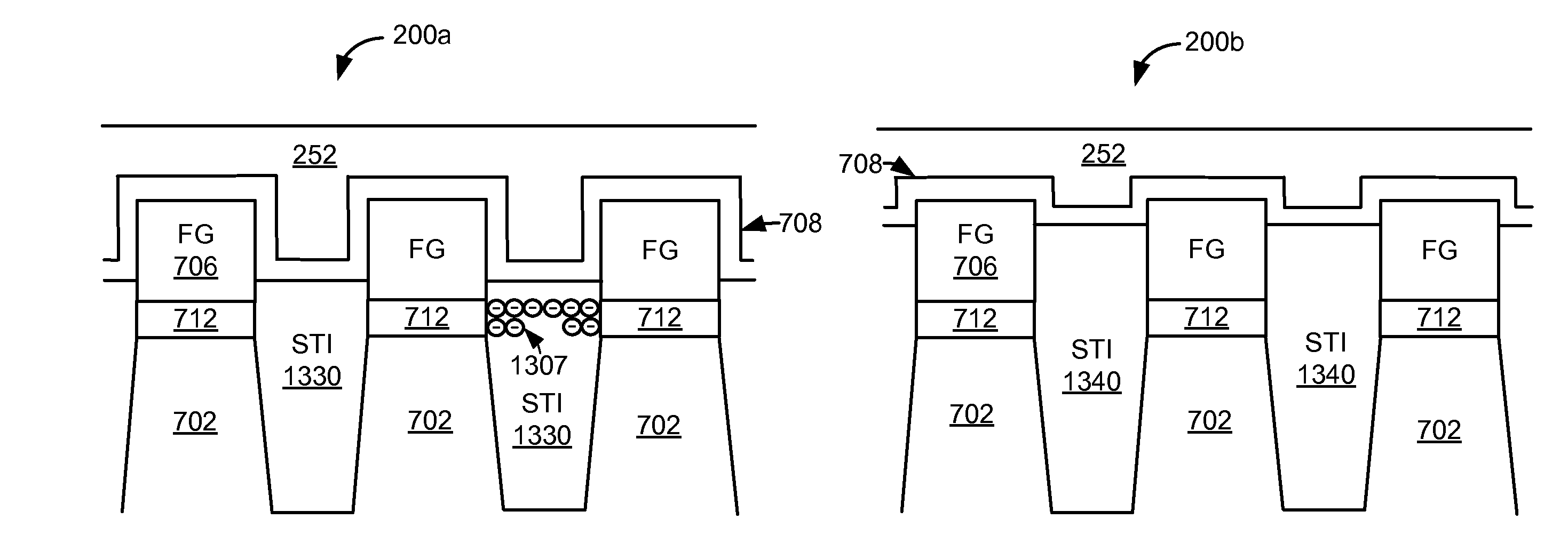
[0040]Techniques are disclosed herein for applying different process steps to SLC blocks than to MLC blocks such that the SLC blocks will have high endurance and the MLC blocks will have high reliability. In some embodiments, different doping is used in the MLC blocks than in the SLC blocks. In some embodiments, different isolation is used in the MLC blocks than in the SLC blocks. Techniques are disclosed herein that apply different read parameters depending on how many times a block has been programmed / erased. Therefore, blocks that have been cycled many times are read using different parameters than blocks that have been cycled fewer times.

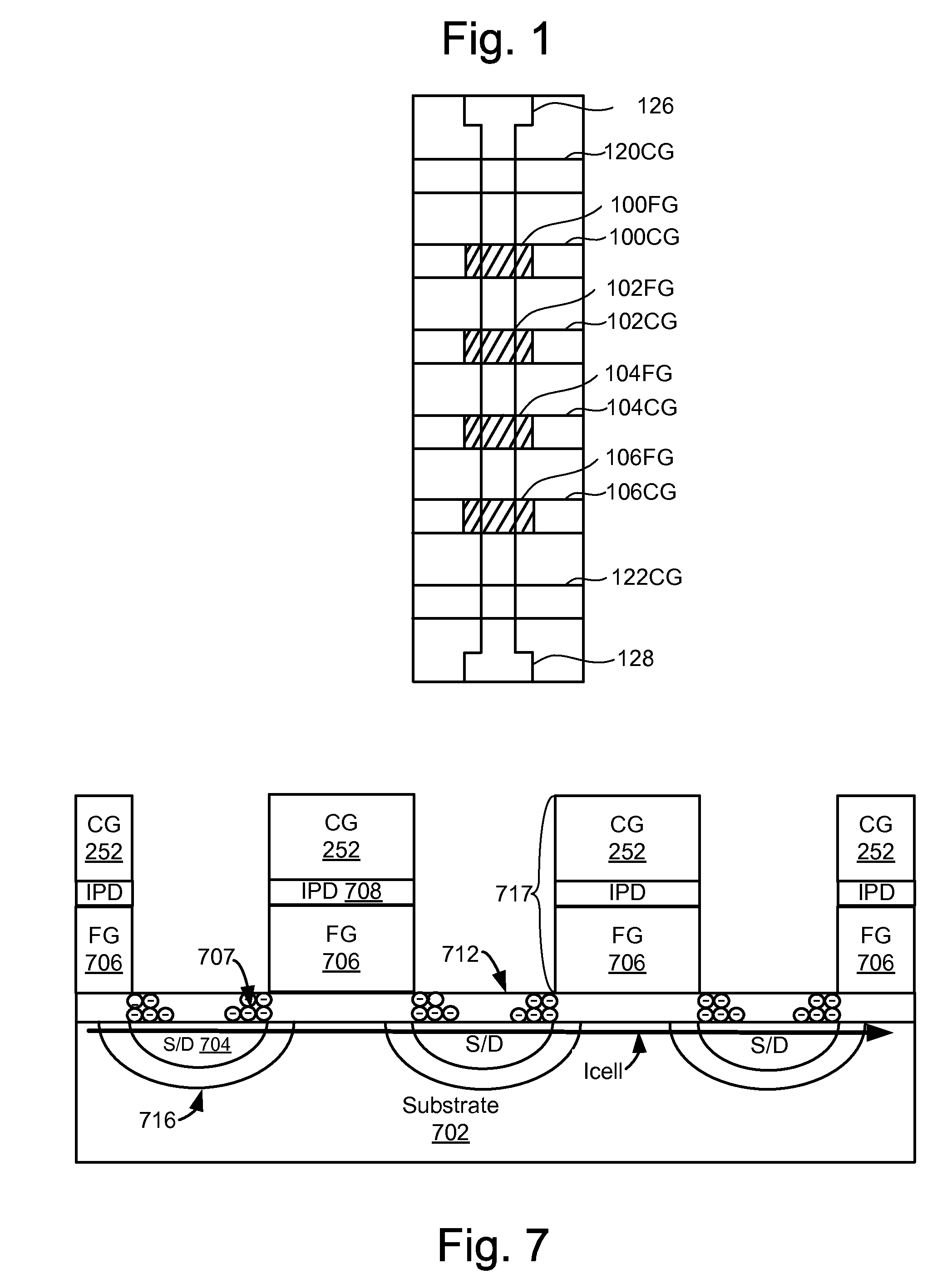
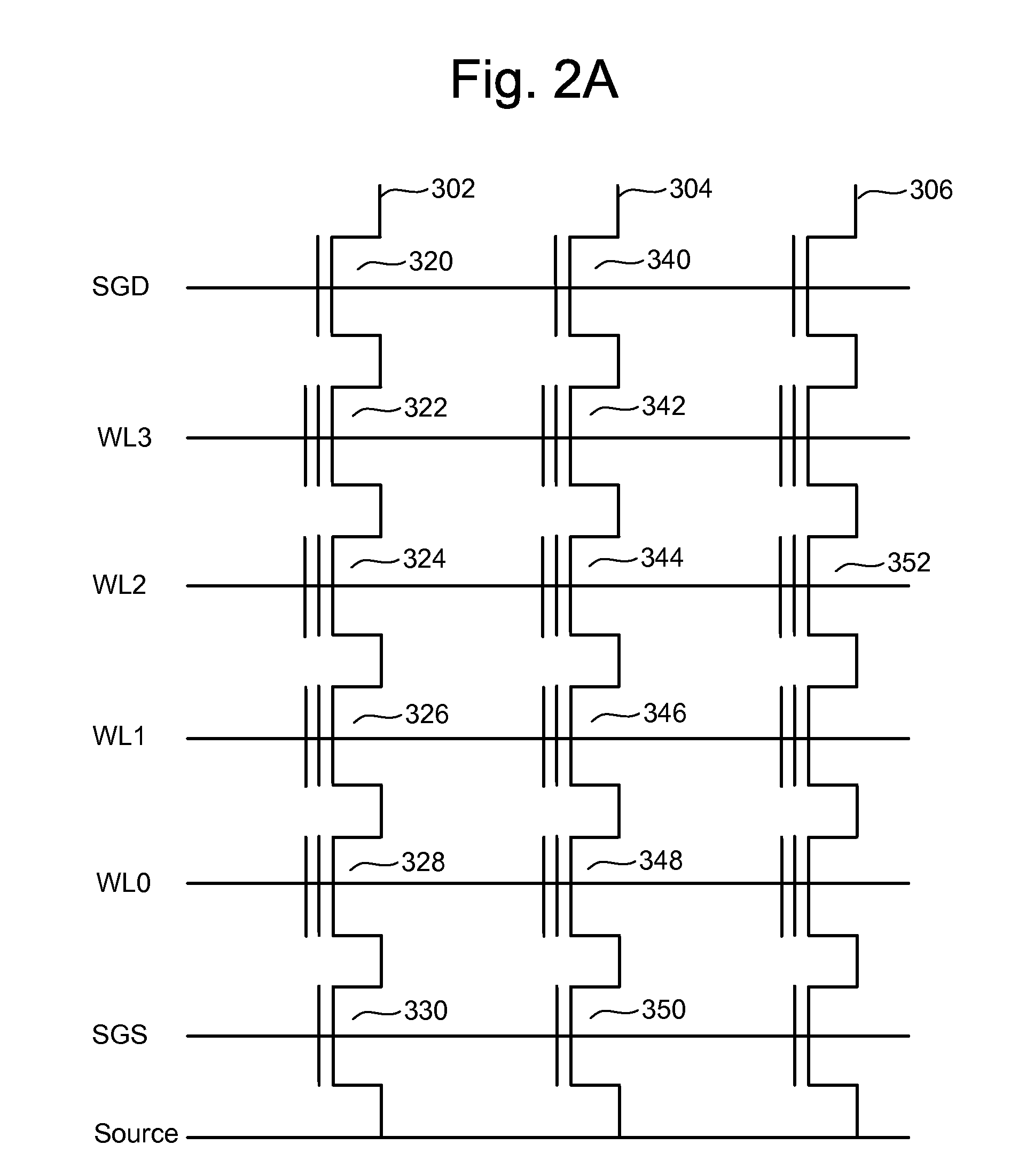
[0041]The techniques described herein are applicable to wide range of memory arrays having memory cells for storing a single bit per cell and memory cells for storing multiple bits per cell. The following is one example NAND architecture. However, techniques described herein are not limited to this example. One example of a flash memory system u...


PUM


Abstract

Techniques are disclosed herein for applying different process steps to single-level cell (SLC) blocks in a memory array than to multi-level cell (MLC) blocks such that the SLC blocks will have high endurance and the MLC blocks will have high reliability. In some aspects, different doping is used in the MLC blocks than the SLC blocks. In some aspects, different isolation is used in the MLC blocks than the SLC blocks. Techniques are disclosed that apply different read parameters depending on how many times a block has been programmed / erased. Therefore, blocks that have been cycled many times are read using different parameters than blocks that have been cycled fewer times.

Description

BACKGROUND OF THE INVENTION[0001]1. Field of the Invention[0002]The present invention relates to non-volatile memory.[0003]2. Description of the Related Art[0004]Semiconductor memory has become increasingly popular for use in various electronic devices. For example, non-volatile semiconductor memory is used in cellular telephones, digital cameras, personal digital assistants, mobile computing devices, non-mobile computing devices and other devices. Electrically Erasable Programmable Read Only Memory (EEPROM) and flash memory are among the most popular non-volatile semiconductor memories. With flash memory, also a type of EEPROM, the contents of the whole memory array, or of a portion of the memory, can be erased in one step, in contrast to the traditional, full-featured EEPROM.[0005]Both the traditional EEPROM and the flash memory utilize a floating gate that is positioned above and insulated from a channel region in a semiconductor substrate. The floating gate is positioned between...

Claims


Application Information

Patent Timeline
Patent Type & Authority Applications(United States)
IPC IPC(8): G11C16/04H01L29/788H01L21/336
CPCG11C2211/5641G11C11/5621
Inventor ITO, FUMITOSHISATO, SHINJI
Owner SANDISK TECH LLC
Why Eureka
Try Eureka