Automatic wire cutting and twisting apparatus

a wire cutting and twisting technology, applied in the field of automatic wire cutting and twisting apparatus, can solve the problems of increasing the requirements of wire cutting and twisting techniques, low productivity, and inability to cut wires, and achieve the effect of improving efficiency, reducing human labor, and precise measures

Inactive Publication Date: 2012-02-23
CHENG UEI PRECISION IND CO LTD
View PDF1 Cites 19 Cited by
  • Summary
  • Abstract
  • Description
  • Claims
  • Application Information

AI Technical Summary

Benefits of technology

[0006]An objective of the present invention is to overcome the problems of the conventional technology discussed above by providing an automatic wire cutting and twisting apparatus, which reduces human labor used, automatically cuts off electrical wires, and realizes precise control of the length of electrical wires so cut off.
[0008]The automatic wire cutting and twisting apparatus according to the present invention is different from the existing technology in that (1) the present invention comprises a wire cutting mechanism that cuts off electrical wires in a mechanical manner and also comprises a wire twisting mechanism that twists the cut wires together so that the present invention realizes automatic cutting and twisting of electrical wires without human intervention, (2) the present invention controls the length of electrical wires cut thereby in a rough measure, where the length of the electrical wires to be cut is roughly determined by a spacing distance between a start-terminal rotation section and an end-terminal rotation section, and a precise measure, where the length is precisely determined through the movement of a slidable dragging section, of which the operation is completely mechanized so that human error occurring in the conventional process for determining the length of electrical wires to be cut is eliminated, (3) the present invention employs a start-terminal rotation section and an end-terminal rotation section to twist electrical wires, where the electrical wires are clamped between the start-terminal rotation section and the end-terminal rotation section and the start-terminal rotation section and the end-terminal rotation section are actuated to rotate in opposite directions so as to perform twisting of the electrical wires, which ensures consistent twisting pitch of the twisted wires, and (4) the present invention comprises a slidable dragging section that moves an end of the electrical wires to an end-terminal rotation section and a start-terminal dragging section that moves an opposite end of the electrical wires to a start-terminal rotation section, so that time used is reduced and efficiency is improved. Thus, the automatic wire cutting and twisting apparatus according to the present invention realizes automatic cutting and twisting of electrical wires with the length of the electrical wires so cut being precisely determined, twisting of the wires being made uniform, human labour being reduced, and efficiency being improved.

Problems solved by technology

With the development and progress of technology, there are increasingly severe requirements for the wire cutting and twisting techniques.
Such an operation is disadvantageous in that (1) a skilled and physically strong operator, which has been well trained for a long time is required for carrying out the cutting and twisting operation, so that this conventional process is generally labor-consuming and time-consuming, (2) electrical wires must be conveyed first for being positioned on the jigs, so that the productivity is low, and (3) the lengths of the wire cut are measured manually, so that the precision might be poor.

Method used


Image

  • Automatic wire cutting and twisting apparatus
  • Automatic wire cutting and twisting apparatus
  • Automatic wire cutting and twisting apparatus

Examples


Embodiment Construction

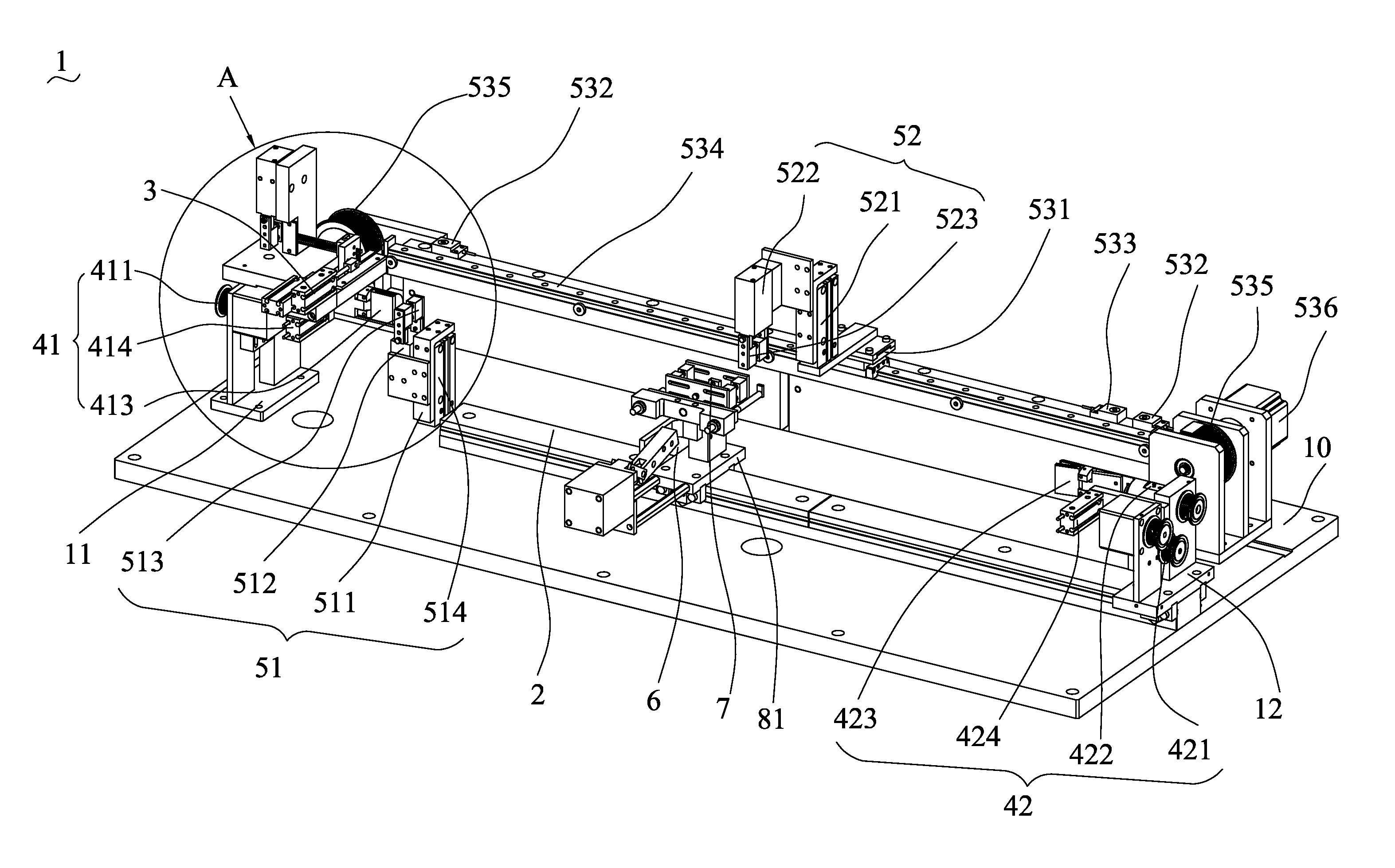
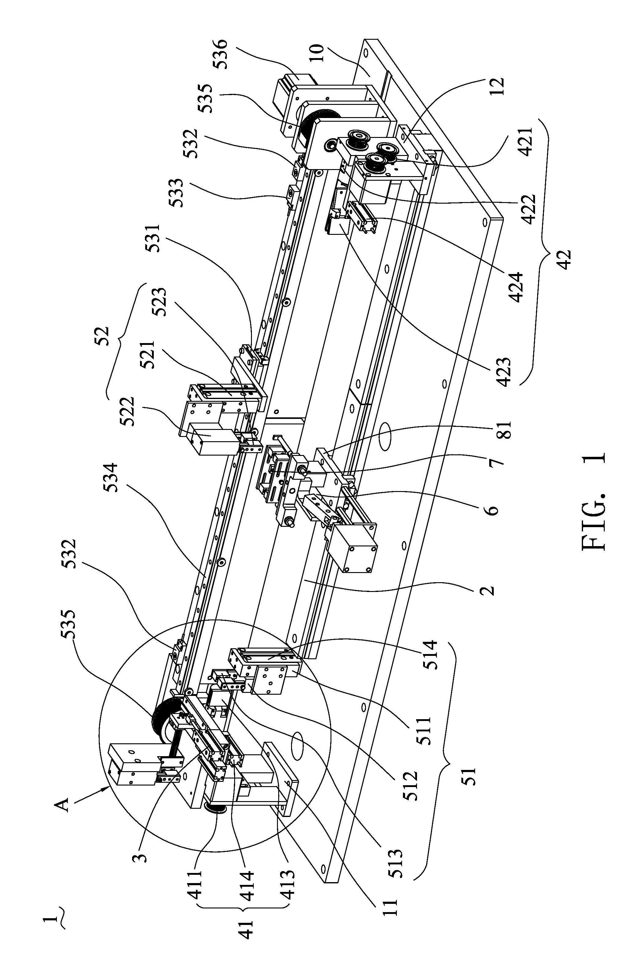
[0016]With reference to the drawings and in particular FIG. 1, the present invention provides an automatic wire cutting and twisting apparatus, generally designated at 1, which is used to cut and twist multiple electrical wires. The automatic wire cutting and twisting apparatus 1 comprises a chassis board 10, a wire cutting mechanism 3, a wire twisting mechanism, a wire dragging mechanism, a wire pick-up mechanism 6, and a cutting and twisting control mechanism (not shown in the drawings). The wire twisting mechanism comprises a start-terminal rotation section 41 and an end-terminal rotation section 42. The wire dragging mechanism comprises a start-terminal dragging section 51 and a slidable dragging section 52. The automatic wire cutting and twisting apparatus 1 may further comprise an intermediate clamping mechanism 7.

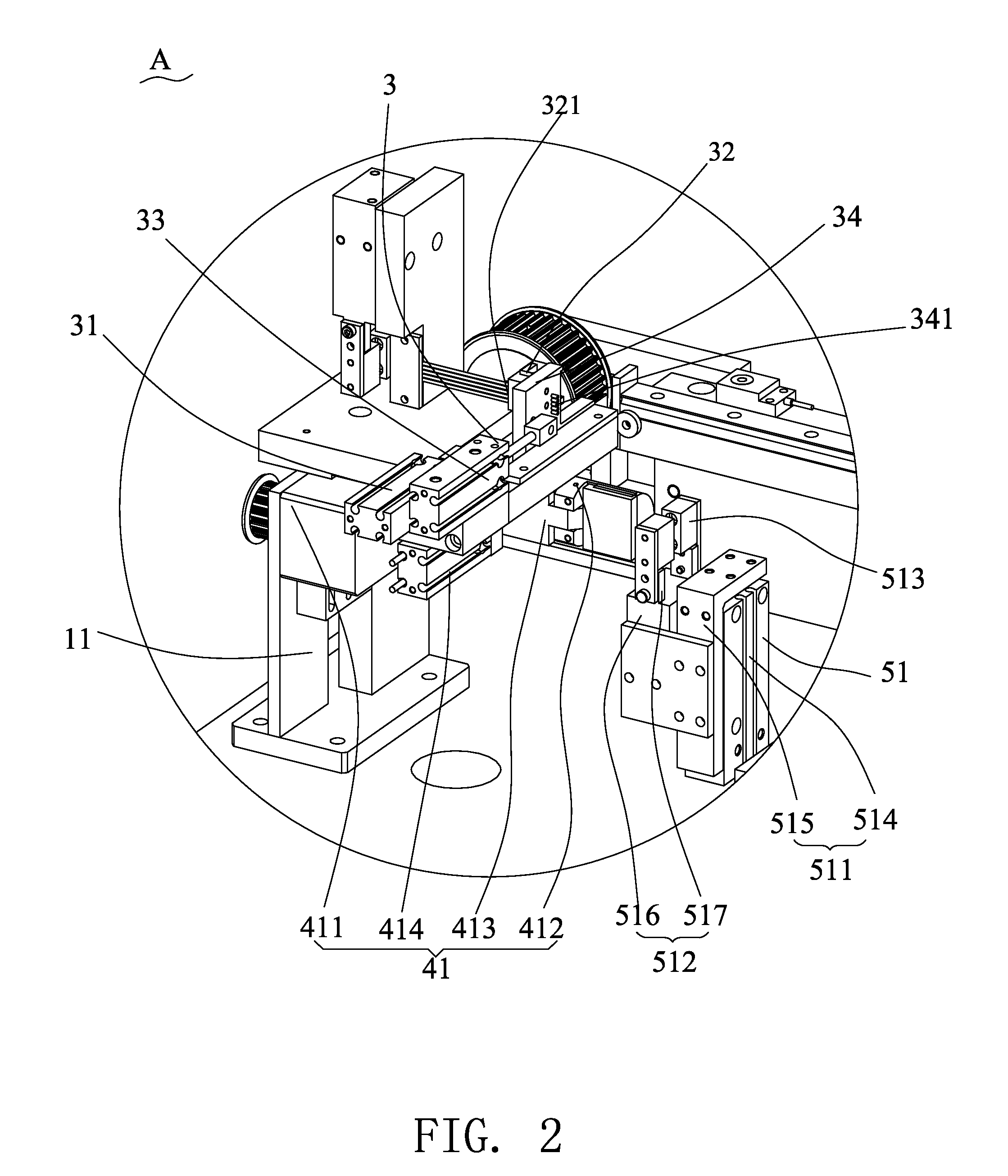
[0017]Referring to FIGS. 1 and 2, the chassis board 10 carries a start-terminal mounting rack 11, an end-terminal mounting rack 12, and a mounting track 2 mounted th...


PUM

PropertyMeasurementUnit
angleaaaaaaaaaa
lengthsaaaaaaaaaa
cut lengthsaaaaaaaaaa

Abstract

An automatic wire cutting and twisting apparatus includes a chassis board on which a start-terminal mounting rack, an end-terminal mounting rack, and a mounting track are mounted. The start-terminal mounting rack opposes a start terminal of the mounting track. The end-terminal mounting rack is position-adjustably coupled to an end terminal of the mounting track. A wire cutting mechanism is mounted on the start-terminal mounting rack and forms ingress and egress for wires. A wire twisting mechanism includes start-terminal and end-terminal rotation sections respectively mounted on the start-terminal and end-terminal mounting racks. A wire dragging mechanism includes a start-terminal dragging section mounted on the chassis board and a slidable dragging section movable above the mounting track. A wire pick-up mechanism is position-adjustably mounted on the mounting track. A cutting and twisting control mechanism is electrically connected to the wire cutting mechanism, the wire twisting mechanism, and the wire dragging mechanism.

Description

BACKGROUND OF THE INVENTION[0001]1. Field of the Invention[0002]The present invention generally relates to a wire cutting and twisting apparatus for cutting and twisting electrical wires, and in particular to an automatic wire cutting and twisting apparatus.[0003]2. The Related Arts[0004]Cutting and twisting electrical wires or cables are operations that are almost indispensable for the wire and cable industry. With the development and progress of technology, there are increasingly severe requirements for the wire cutting and twisting techniques. Some existing work shops still employs manual operations to cut and twist electrical wires, where an operator first cuts desired lengths of electrical wires by applying jigs of simple structures and then twists together two or more of the cut lengths of electrical wire. Such an operation is disadvantageous in that (1) a skilled and physically strong operator, which has been well trained for a long time is required for carrying out the cutti...

Claims


Application Information

Patent Timeline
Patent Type & Authority Applications(United States)
IPC IPC(8): B21F99/00
CPCD07B7/16H01B13/02H01B13/012
Inventor ZHANG, SHAO-BOCHOU, LUNG-CHUANCHEN, SUNG-LINWU, XIAO-LINZOU, ZAI--WEI
Owner CHENG UEI PRECISION IND CO LTD
Why Eureka
Try Eureka