Glow plug and method for connecting a pin made of functional ceramic to a metal sleeve

a technology of functional ceramics and glow plugs, which is applied in the direction of mechanical equipment, machines/engines, light and heating apparatus, etc., can solve the problems of premature failure of glow plugs and high mechanical properties, and achieve simple and cost-effective production of glow plugs, reliable and robust connection, and improved centered position.

Active Publication Date: 2012-02-23
BORGWARNER BERU SYST
View PDF1 Cites 11 Cited by
  • Summary
  • Abstract
  • Description
  • Claims
  • Application Information

AI Technical Summary

Benefits of technology

[0003]In the glow plug according to the invention, the glow pin is pressed into the metal sleeve. By pressing, a reliable and robust connection can be established between the ceramic glow pin and the metal sleeve in a cost-effective manner. Advantageously, in this way, simple and cost-effective production of the glow plug and an improvement in the centered position, coaxiality and longitudinal dimensional accuracy are enabled. As a result, the risk of short circuits due to solder bridges can be avoided. In addition, an extended service life can be achieved with a glow plug according to the invention. During brazing, high mechanical stresses occur due to different coefficients of expansion of the metal sleeve, brazing material and glow pin, which favor cracking and therefore can result in premature failure of the glow plug. Due to the different thermal coefficients of expansion of the metal sleeve, brazing material and glow pin, in particular an uneven coverage with brazing material can bring about shear forces, which produce cracks. Temperature-related stresses and the associated risk of cracking can advantageously be prevented according to the invention. It is furthermore advantageous that during operation the combustion chamber pressure acts in the pressing-in direction and thereby stabilizes the press fit.

Problems solved by technology

During brazing, high mechanical stresses occur due to different coefficients of expansion of the metal sleeve, brazing material and glow pin, which favor cracking and therefore can result in premature failure of the glow plug.
Due to the different thermal coefficients of expansion of the metal sleeve, brazing material and glow pin, in particular an uneven coverage with brazing material can bring about shear forces, which produce cracks.

Method used


Image

  • Glow plug and method for connecting a pin made of functional ceramic to a metal sleeve
  • Glow plug and method for connecting a pin made of functional ceramic to a metal sleeve
  • Glow plug and method for connecting a pin made of functional ceramic to a metal sleeve

Examples


Embodiment Construction

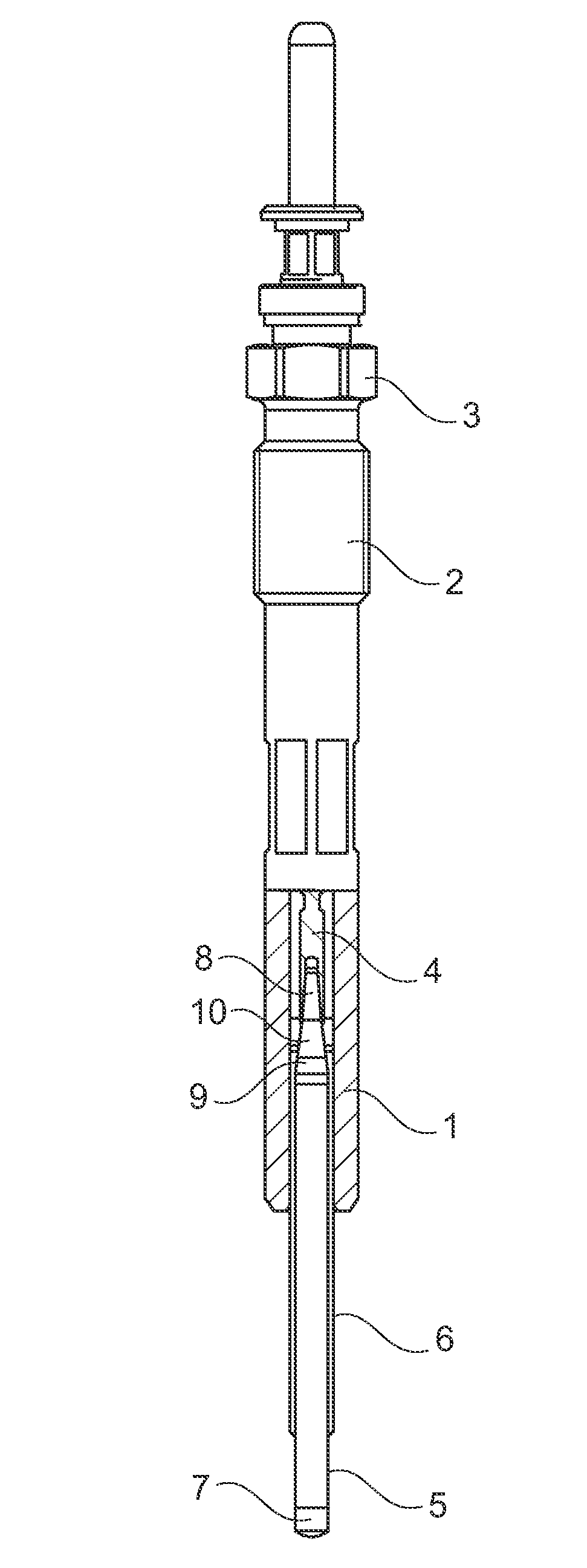
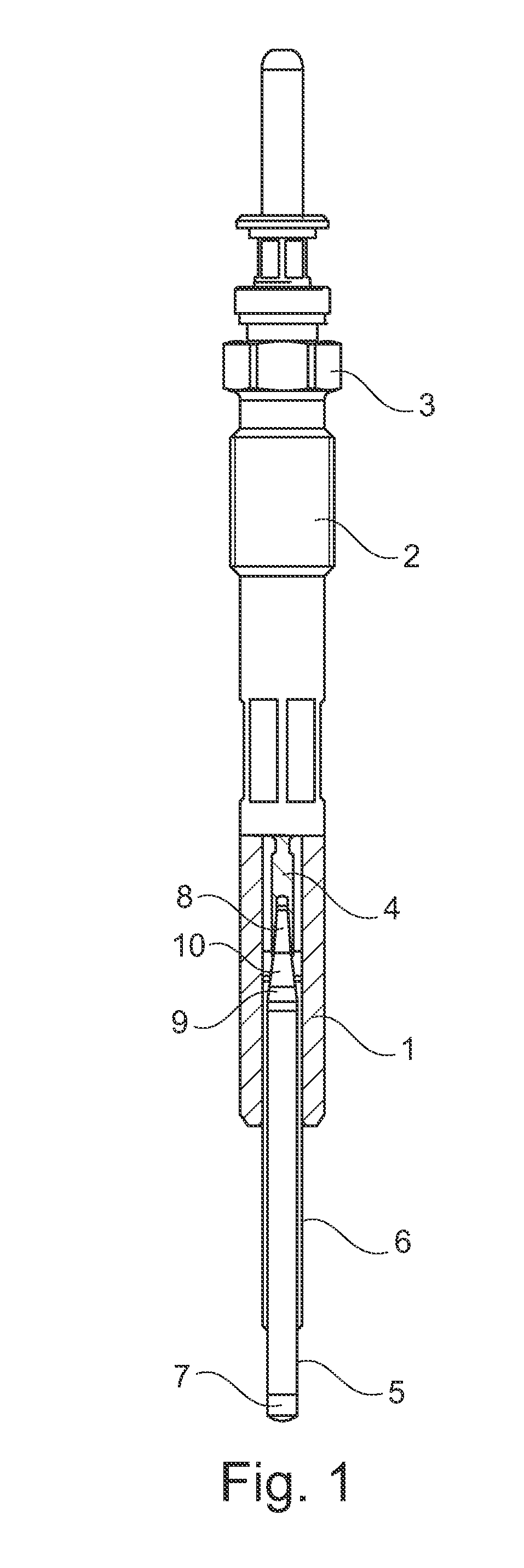
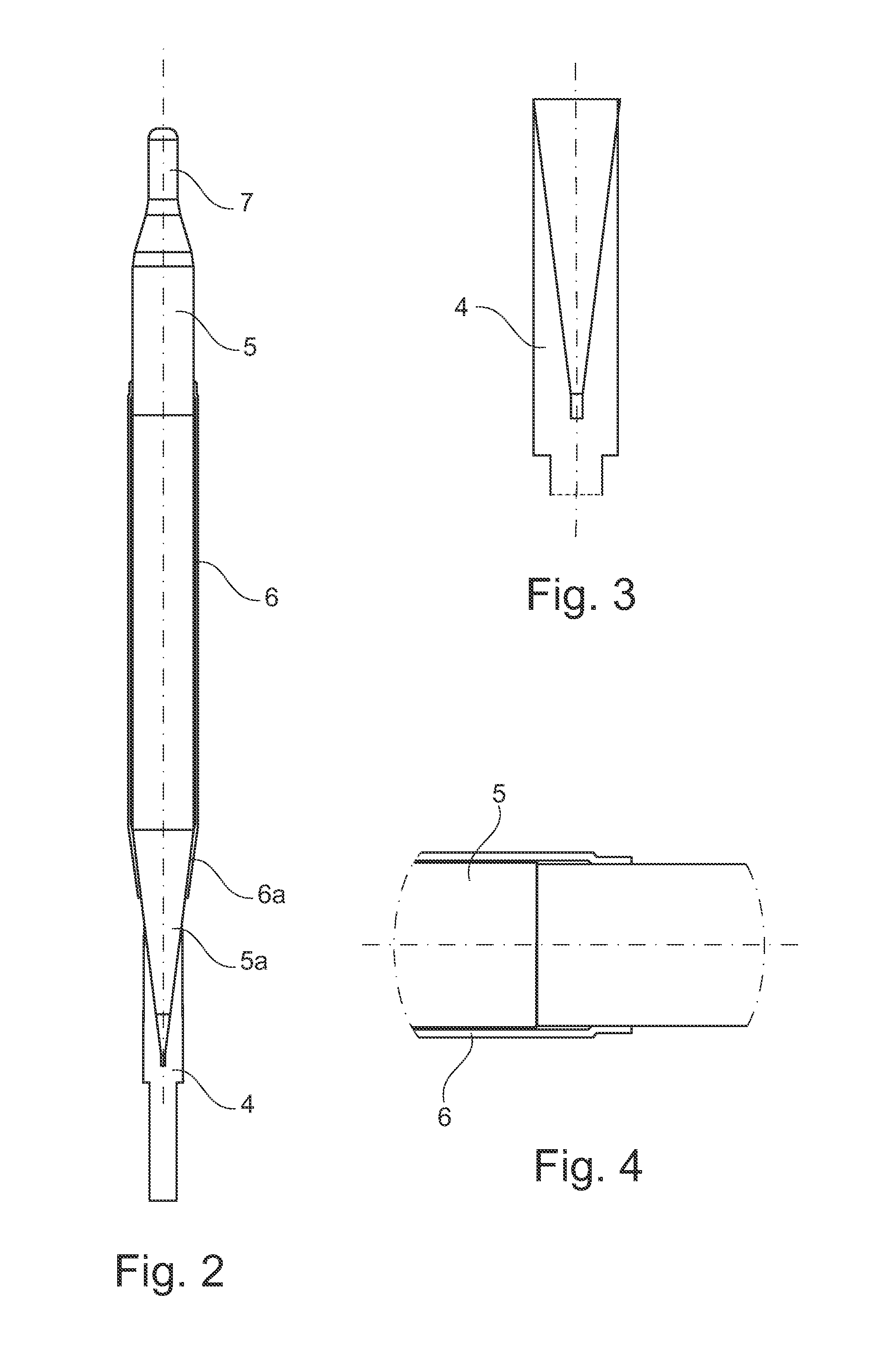
[0025]FIG. 1 is a schematic illustration of an exemplary embodiment of a glow plug in a partially cut view. The glow plug comprises a metallic housing 1 having an external thread 2 and a hexagon 3. In the housing 1, a metallic inner conductor 4 is disposed, which is connected to the rear end of a ceramic glow pin 5 facing away from the combustion chamber. The ceramic glow pin 5 is pressed into a metal sleeve 6, which is inserted into the housing 1. Both ends of the glow pin 5 protrude from the metal sleeve 6 and the glow pin has a glow tip 7 at the front end thereof on the combustion chamber side.

[0026]The metal sleeve 6 is preferably pressed into the housing, however it can also be brazed or welded to the housing 1, for example. At the front end, the rod-shaped metallic inner conductor 4 has an opening into which the rear end of the glow pin 5 projects. The rear end of the glow pin 5 is preferably pressed into the inner conductor 4. It is also possible, however, to braze the inner ...


PUM

PropertyMeasurementUnit
angleaaaaaaaaaa
diameteraaaaaaaaaa
bezel anglesaaaaaaaaaa

Abstract

The invention relates to a glow plug comprising a housing in which an inner conductor is disposed, a metal sleeve which is inserted into the housing, and a ceramic glow pin which is disposed in the metal sleeve, wherein the two ends of the glow pin protrude from the metal sleeve and the rear end of the pin is connected to the inner conductor, and wherein the metal sleeve has a tapering section at the rear end, the section enclosing a tapering section of the glow pin. According to the invention, the glow pin is pressed into the metal sleeve. The invention further relates to a method for connecting a pin made of functional ceramic to a metal sleeve.

Description

[0001]Glow plugs are known from DE 10 2006 016 566 A1. In order to produce the known glow plug, a metal sleeve and a glow pin, and an inner conductor and a glow pin, are brazed to each other. This creates the risk that solder bridges may form, which can result in short circuits.[0002]It is the object of the invention to simplify the production of a glow plug of the type mentioned above and find a way to better avoid short circuits.SUMMARY OF THE INVENTION[0003]In the glow plug according to the invention, the glow pin is pressed into the metal sleeve. By pressing, a reliable and robust connection can be established between the ceramic glow pin and the metal sleeve in a cost-effective manner. Advantageously, in this way, simple and cost-effective production of the glow plug and an improvement in the centered position, coaxiality and longitudinal dimensional accuracy are enabled. As a result, the risk of short circuits due to solder bridges can be avoided. In addition, an extended serv...

Claims


Application Information

Patent Timeline
Patent Type & Authority Applications(United States)
IPC IPC(8): F23Q7/22H01C17/00
CPCF23Q7/001Y10T29/49083H05B3/141F02P19/00
Inventor CHENG, YUEKASIMIRSKI, HANS PETERMUELLER, HELMUTSAJATOVIC, DRAZEN
Owner BORGWARNER BERU SYST
Why Eureka
Try Eureka