Automation Control System Components with Electronic Keying Features

a technology of automatic control system and electronic keying, applied in the direction of programme control, coupling device connection, instruments, etc., can solve the problems of unexpected control problems, inadvertent mismatches of i/o modules and terminal blocks,

Active Publication Date: 2012-02-23
ROCKWELL AUTOMATION TECH
View PDF4 Cites 23 Cited by
  • Summary
  • Abstract
  • Description
  • Claims
  • Application Information

AI Technical Summary

Benefits of technology

[0005]The present invention addresses shortcomings of traditional I / O devices by providing electronic keying features that may be stored within one of the components (e.g., the I / O modules, the terminal blocks, the bases, and so forth) of the I / O devices, and which may be read or detected by electronic key identification circuitry in one of the other components of the I / O devices. More specifically, the electronic keying features may include unique identification keys that may be read or detected by the electronic key identification circuitry to determine whether the components (e.g., a paired I / O module and terminal block) are associated with each other and intended to operate together. For example, in certain embodiments, the electronic key feature may be disposed within a terminal block and the electronic key identification circuitry may be disposed within an I / O module, or vice versa. In addition, in certain embodiments, the electronic key feature and / or the electronic key identification circuitry may be removable from their respective component of the I / O device.

Problems solved by technology

As such, inadvertent mismatches of I / O modules and terminal blocks may occur.
As a result, unexpected control issues may arise due to such mismatches.

Method used


Image

  • Automation Control System Components with Electronic Keying Features
  • Automation Control System Components with Electronic Keying Features
  • Automation Control System Components with Electronic Keying Features

Examples


Embodiment Construction

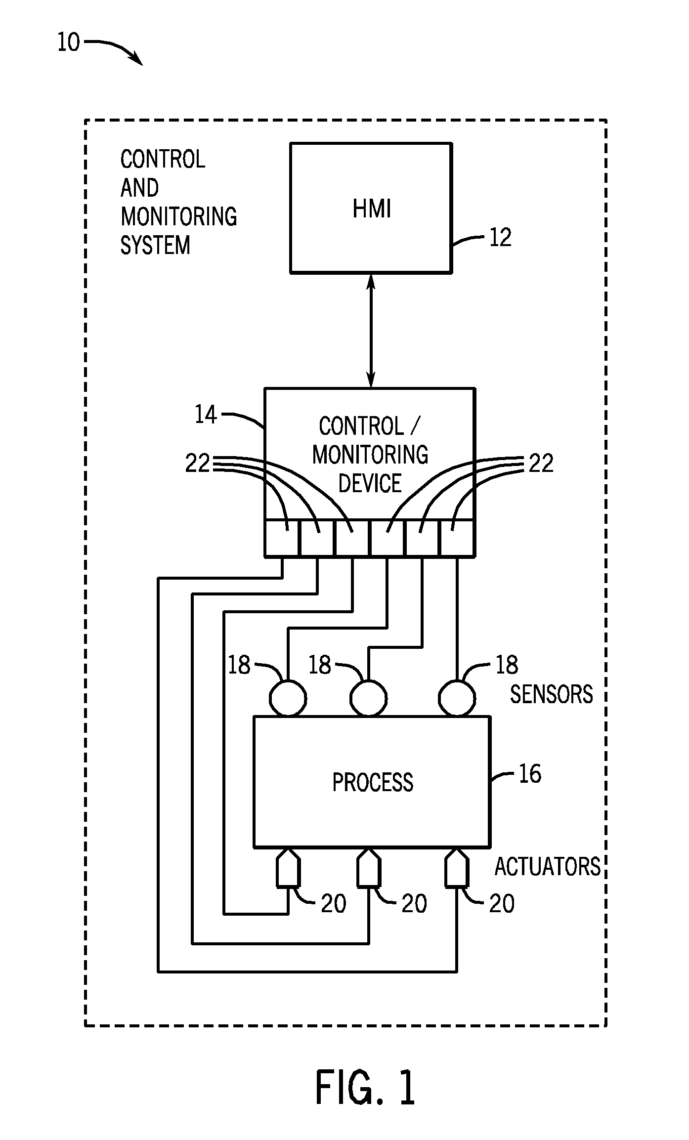
[0017]FIG. 1 is a diagrammatical representation of an exemplary control and monitoring system adapted to interface with networked components and configuration equipment in accordance with embodiments of the present techniques. The control and monitoring system is generally indicated by reference numeral 10. Specifically, the control and monitoring system 10 is illustrated as including a human machine interface (HMI) 12 and an automation controller or control / monitoring device 14 adapted to interface with components of a process 16. It should be noted that such an interface in accordance with embodiments of the present techniques may be facilitated by the use of certain network strategies. Indeed, an industry standard network may be employed, such as DeviceNet, to enable data transfer. Such networks permit the exchange of data in accordance with a predefined protocol, and may provide power for operation of networked elements.

[0018]The process 16 may take many forms and include device...


PUM

PropertyMeasurementUnit
resistanceaaaaaaaaaa
voltageaaaaaaaaaa
timeaaaaaaaaaa

Abstract

Systems and methods are provided for utilizing electronic keying features stored within one of the components (e.g., I / O modules, terminal blocks, bases, and so forth) of I / O devices, and which may be read or detected by electronic key identification circuitry in one of the other components of the I / O devices. More specifically, the electronic keying features may include unique identification keys that may be read or detected by the electronic key identification circuitry to determine whether the components (e.g., a paired I / O module and terminal block) are associated with each other and intended to operate together. For example, in certain embodiments, the electronic key feature may be disposed within a terminal block and the electronic key identification circuitry may be disposed within an I / O module, or vice versa. In addition, in certain embodiments, the electronic key feature and / or the electronic key identification circuitry may be removable from their respective component of the I / O device.

Description

CROSS REFERENCE TO RELATED APPLICATIONS[0001]This application claims priority of U.S. Provisional Patent Application No. 61 / 375,587, filed Aug. 20, 2010, which is herein incorporated in its entirety by reference.BACKGROUND[0002]The invention relates generally to the field of automation control systems, such as those used in industrial and commercial settings. More particularly, embodiments of the present invention relate to techniques for providing, accessing, configuring, operating, or interfacing with input / output (I / O) devices that are configured for coupling and interaction with an automation controller.[0003]Automation controllers are special purpose computers used for controlling industrial automation and the like. Under the direction of stored programs, a processor of the automation controller examines a series of inputs (e.g., electrical input signals to the automation controller) reflecting the status of a controlled process and changes outputs (e.g., electrical output sign...

Claims


Application Information

Patent Timeline
Patent Type & Authority Applications(United States)
IPC IPC(8): G06F17/00
CPCH05K7/1468H05K7/1484Y10T29/49117H01R13/635H01R13/62H01R13/629G05B19/054G05B19/056G05B2219/21092G05B2219/25314G05B2219/25452H05K7/1474G06F13/10G06F9/44505G05B15/02
Inventor VAZACH, JOSEPH G.WEHRLE, DAVID S.BODMANN, DOUGLAS R.KRETSCHMANN, ROBERT J.SICHNER, GREGG M.
Owner ROCKWELL AUTOMATION TECH
Why Eureka
Try Eureka