Clamp assembly

a technology of clamping and assembly, which is applied in the direction of couplings, machine supports, fishing, etc., can solve the problems of large noise, large-scale size, and large noise of horizontal axis wind turbines

Inactive Publication Date: 2012-02-23
JACOB SAJAN JOSEPH
View PDF17 Cites 6 Cited by
  • Summary
  • Abstract
  • Description
  • Claims
  • Application Information

AI Technical Summary

Problems solved by technology

However, these horizontal axis wind turbines have several drawbacks.
For example, the wind direction may impact the ability of a horizontal axis wind turbines to operate efficiently as the horizontal axis wind turbines must be rotated to face the wind, the large-scale arc of ro

Method used


Image

  • Clamp assembly
  • Clamp assembly
  • Clamp assembly

Examples


Embodiment Construction

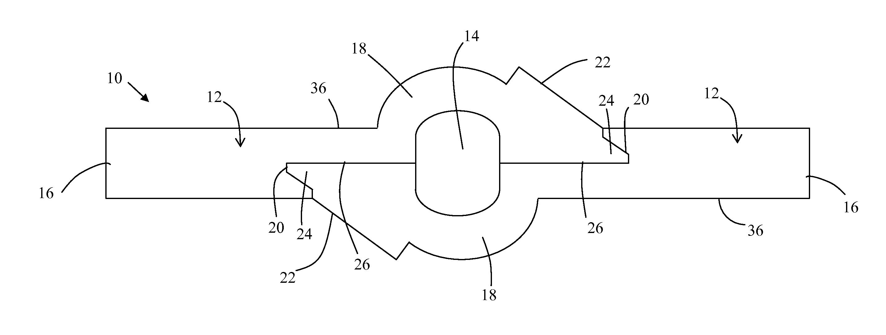
[0021]Embodiments of the invention provide a clamp assembly for mounting rods or other load-bearing structures substantially perpendicularly to a shaft, such as a rotor shaft or an axle. For example, a clamp assembly of the present invention may be used for mounting rods to the rotor shaft of a wind turbine, where the rods are substantially perpendicular to the rotor shaft and are used to support the blades of the wind turbine. However, the inventive clamp assemblies described herein are by no means limited for use in the construction of wind turbines. Other suitable applications will be apparent to those of skill in the art after reading the following description of the exemplary embodiments.

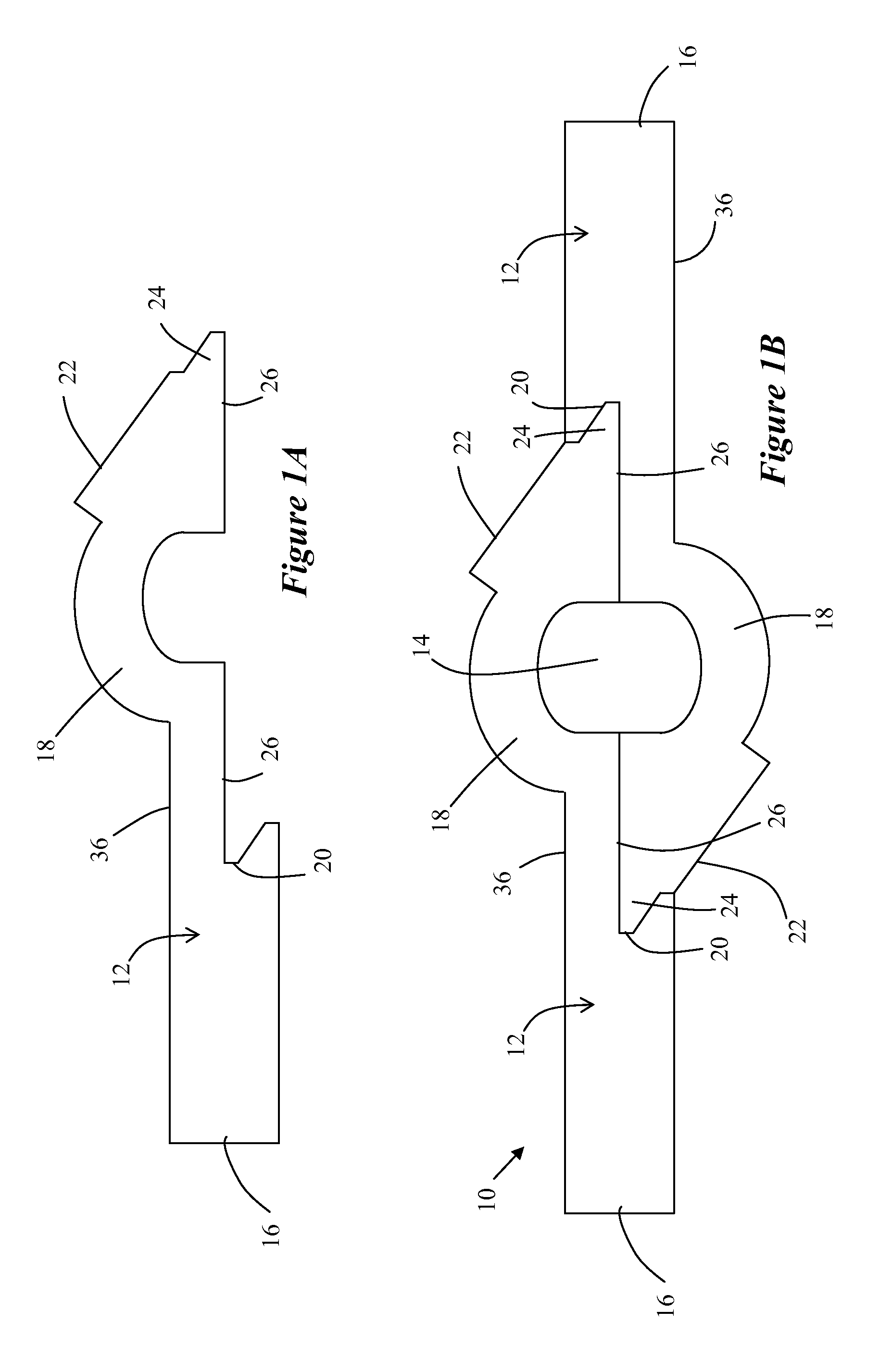
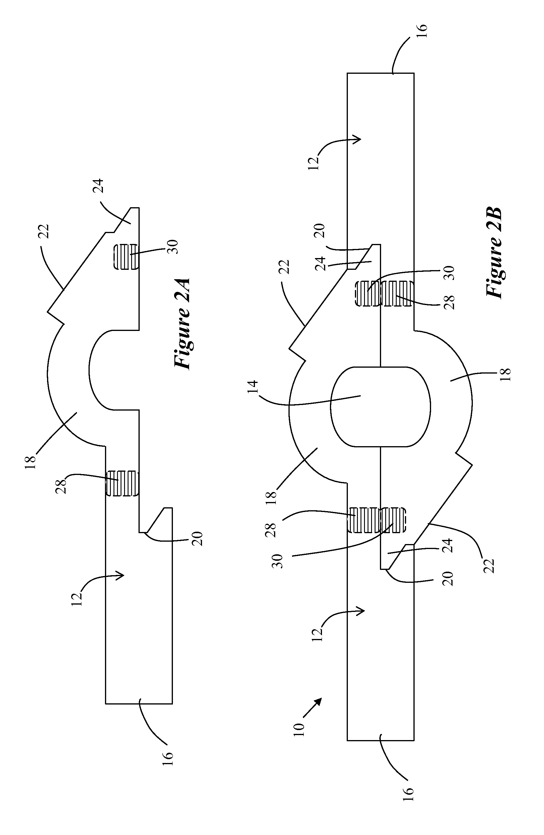
[0022]Exemplary embodiments of the present invention will hereinafter be described with reference to the drawings, in which like numerals are used to indicate like elements. For the sake of convenience, the drawings are not drawn to scale or with precise perspective and any reference herein to ...


PUM


Abstract

A clamp assembly comprising two brackets. Each bracket may include an elongated end, a curved section adjacent the elongated end, a channel formed by the curved section, and a mating surface adjacent the channel. When the mating surfaces of each bracket are in mating contact with each other, the channels of each bracket are substantially aligned with each other to form a shaft aperture. The brackets may be fitted together via a tongue and groove configuration and are coupled by way of mechanical fasteners at connection points on each bracket. Each bracket may comprise a coupling area that is configured to engage a mechanical fastener. The clamp assembly mounts to a shaft comprising a plurality of notched segments, wherein each notched segment has a cross-sectional shape that is substantially similar to the shaft aperture cross-sectional shape. The shape of the shaft aperture and the cross-sectional shape of the shaft may be a rounded rectangle, so that the mounted clamp assembly will not rotate around the shaft when rotational force is applied thereto. The plurality of notched segments may be rotated angularly relative to each other.

Description

FIELD OF THE INVENTION[0001]The field of the invention relates to clamps for mounting rods or other load-bearing structures substantially perpendicularly to a shaft.BACKGROUND[0002]Wind is an increasing source of energy for driving wind turbines, windmills, and the like, for the production of electrical power. Traditionally, horizontal axis wind turbines were used to power electric generators. However, these horizontal axis wind turbines have several drawbacks. For example, the wind direction may impact the ability of a horizontal axis wind turbines to operate efficiently as the horizontal axis wind turbines must be rotated to face the wind, the large-scale arc of rotation poses a safety threat to aircraft and birds, large-scale horizontal axis wind turbines create a substantial amount of noise due to the speed of rotation at the tips of the blades, and the large-scale size is impractical for single home or other small-scale applications.[0003]In recent years, there has been a trans...

Claims


Application Information

Patent Timeline
IPC IPC(8): F16B2/02F16M13/00
CPCF16B3/00Y10T24/44017F16B9/026F16D1/076
Inventor JACOB, SAJAN "JOSEPH"
Owner JACOB SAJAN JOSEPH
Why Eureka
Try Eureka