
Delay line interferometer with liquid crystal tuning element

a technology of liquid crystal tuning and interferometer, which is applied in the direction of light demodulation, electromagnetic receivers, instruments, etc., can solve the problems that the production of optical systems capable of accurately demodulating phase modulated signals is becoming increasingly difficult, and achieves the effect of reducing polarization-dependent frequency shi

Inactive Publication Date: 2012-02-23
II VI DELAWARE INC
View PDF2 Cites 14 Cited by
  • Summary
  • Abstract
  • Description
  • Claims
  • Application Information

AI Technical Summary

Benefits of technology

The present invention provides a delay line interferometer with a liquid-crystal (LC) tuning element that allows for quickly tuning the phase difference between two optical signals separated from a phase-modulated input signal, so that the two optical signals can be coherently recombined to interfere with each other and produce one or more intensity-modulated optical signals. The LC tuning element reduces polarization-dependent frequency shift without the use of additional high-precision optical elements and / or coatings. The interferometer can be used to demodulate a phase-modulated optical signal by introducing a substantially one-bit time delay in one of the light beams and modulating the phase of the other light beam with the LC tuning element to create interference in the time domain between the two light beams.

Problems solved by technology

As the bit rates used in optical communication systems increase into the gigabits per second (Gbps) regime, optical systems capable of accurately demodulating phase modulated signals become increasingly difficult to manufacture due to the precise alignment and sizing of optical components and coatings required.

Method used


Image

  • Delay line interferometer with liquid crystal tuning element
  • Delay line interferometer with liquid crystal tuning element
  • Delay line interferometer with liquid crystal tuning element

Examples


Embodiment Construction

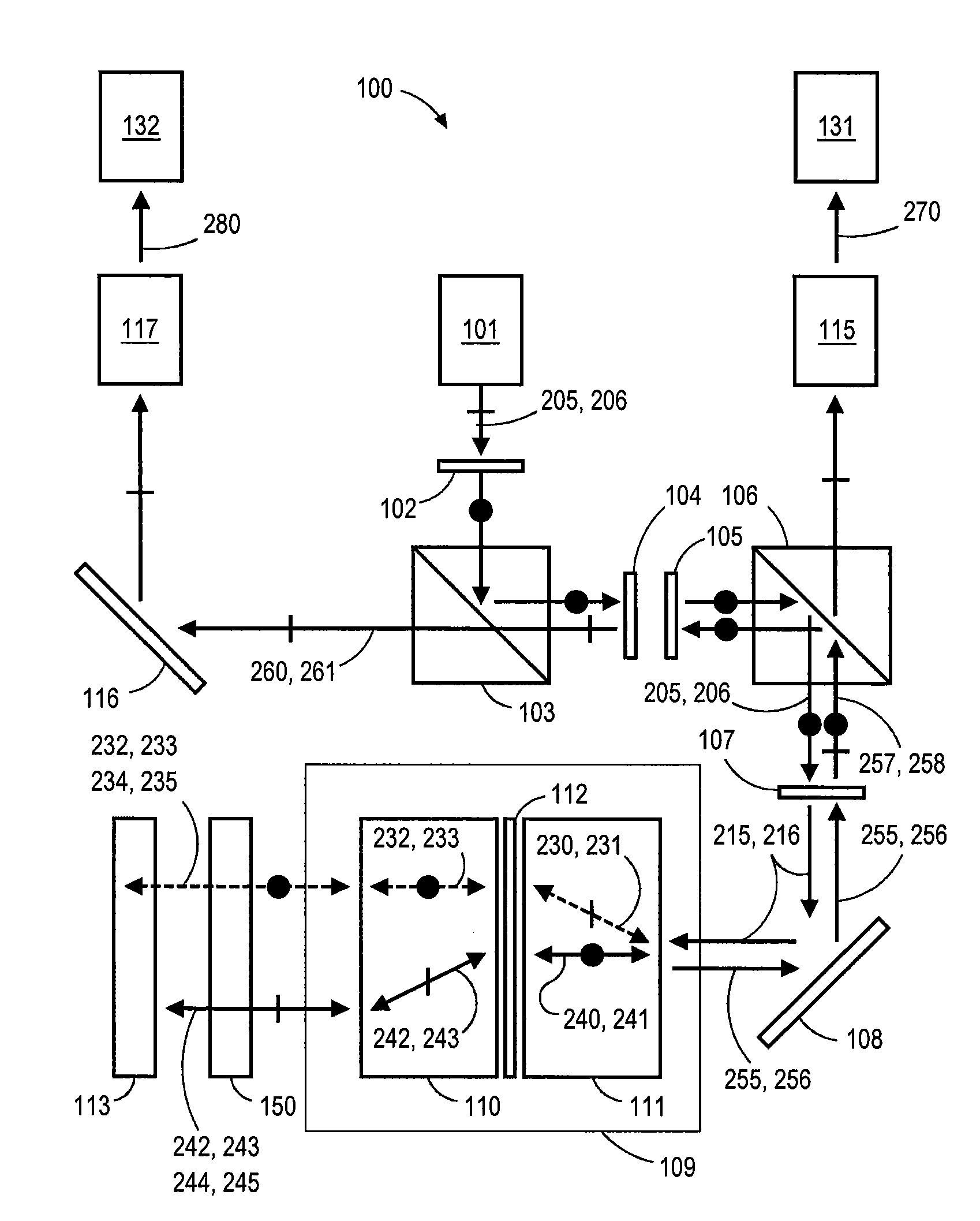
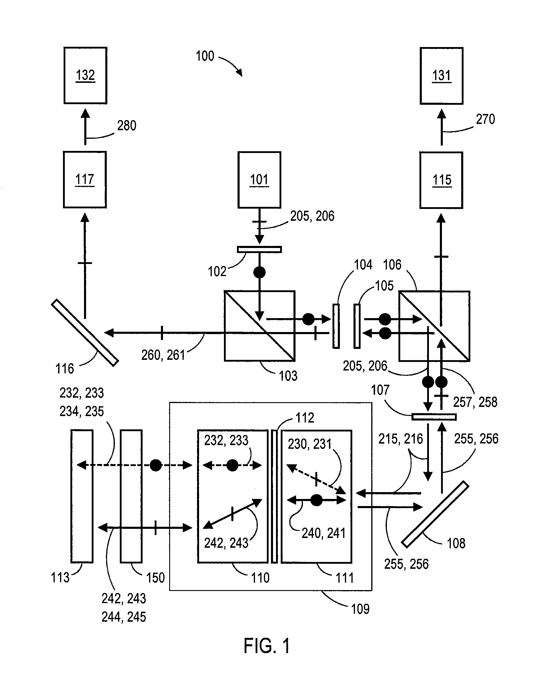
[0020]FIG. 1 schematically illustrates a delay line interferometer 100 with a liquid crystal (LC) tuning element 150, according to embodiments of the invention. Delay line interferometer 100 includes an input collimator 101, output collimators 115, 117, polarizing beam splitters 103, 106, mirrors 108, 116, a separating and combining subassembly 109, LC tuning element 150, an optical delay element 113, and assorted polarization plates, i.e., a 45 degree half wave plate 102, a Faraday rotator 104, a 22.5 degree half wave plate 105, and a quarter wave plate 107. Delay line interferometer 100 is configured to receive a phase-modulated input signal 120, such as a DPSK signal, separate phase-modulated input signal 120 into two equal-intensity beams, introducing a substantially one-bit time delay between the two equal-intensity beams, and recombining the two beams to produce constructive or destructive interference in the time domain for each information bit of phase-modulated input signal...


PUM

PropertyMeasurementUnit
optical pathaaaaaaaaaa
response timeaaaaaaaaaa

Abstract

A delay line interferometer is configured with a liquid-crystal (LC) tuning element as a phase modulator for demodulating a phase-modulated input signal. The LC tuning element allows for quickly tuning the phase difference between two optical signals separated from the phase-modulated input signal, so that the two optical signals can be coherently recombined to interfere with each other and produce one or more intensity-modulated optical signals. In some embodiments, the LC tuning element is configured to reduce polarization-dependent frequency shift without the use of additional high-precision optical elements and / or coatings.

Description

BACKGROUND OF THE INVENTION[0001]1. Field of the Invention[0002]Embodiments of the present invention relate generally to optical communication systems and components and, more particularly, to a delay-line interferometer with a liquid crystal tuning element.[0003]2. Description of the Related Art[0004]Differential phase-shift keying (DPSK) is a form of phase modulation used in optical communication systems that conveys data in an optical signal by changing the phase of the carrier wave. Optical communication systems commonly use signal phase modulation, and particularly DPSK, for transmission since phase modulation is strongly resistant to signal degradation caused by chromatic dispersion or polarization mode dispersion in a transmission line. In order to convert such a phase-keyed signal into an amplitude-keyed signal, i.e., an optical-intensity-keyed signal, delay line interferometers are used in optical communication systems as signal demodulators. Delay line interferometers are ...

Claims


Application Information

Patent Timeline
Patent Type & Authority Applications(United States)
IPC IPC(8): G02F2/00G02B27/28G02F1/13363
CPCG02B27/283
Inventor WANG, RUIBOSUN, RUIPENG
Owner II VI DELAWARE INC
Learn More