Aircraft GPU connection method and apparatus

a technology for connecting gpu and aircraft, which is applied in the direction of electrical discharge lamps, coupling device connections, transportation and packaging, etc., can solve the problems of obviating the need to use aircraft's inefficient gpu, consuming a significant amount of fuel, and relatively inefficient gpu devices, so as to achieve efficient and safe connection of tractor-mounted gpu

Inactive Publication Date: 2012-02-23
JBT AEROTECH CORP
View PDF11 Cites 11 Cited by
  • Summary
  • Abstract
  • Description
  • Claims
  • Application Information

AI Technical Summary

Benefits of technology

[0009]The present invention provides a method and apparatus for efficiently and safely connecting the tractor-mounted GPU to the aircraft's GPU receptacle. In one embodiment of the invention, the process of connecting the GPU cable to the aircraft's GPU receptacle i...

Problems solved by technology

However, APU's are relatively inefficient devices which consume a significant amount of fuel.
Thus, the aircraft can be connected to the tractor-mounted GPU to provide power to the aircraft during the tow, which obviates the need to use the aircraft's inefficient APU.
The GPU cable and connector are relatively heavy and require considerable force to be properly inserted into the receptacle.
Moreover, in the case of a tall aircraft the operator may have to stretch to reach the GPU receptacle, and in the case of a low aircraft the operator may have to cro...

Method used


Image

  • Aircraft GPU connection method and apparatus
  • Aircraft GPU connection method and apparatus
  • Aircraft GPU connection method and apparatus

Examples


first embodiment

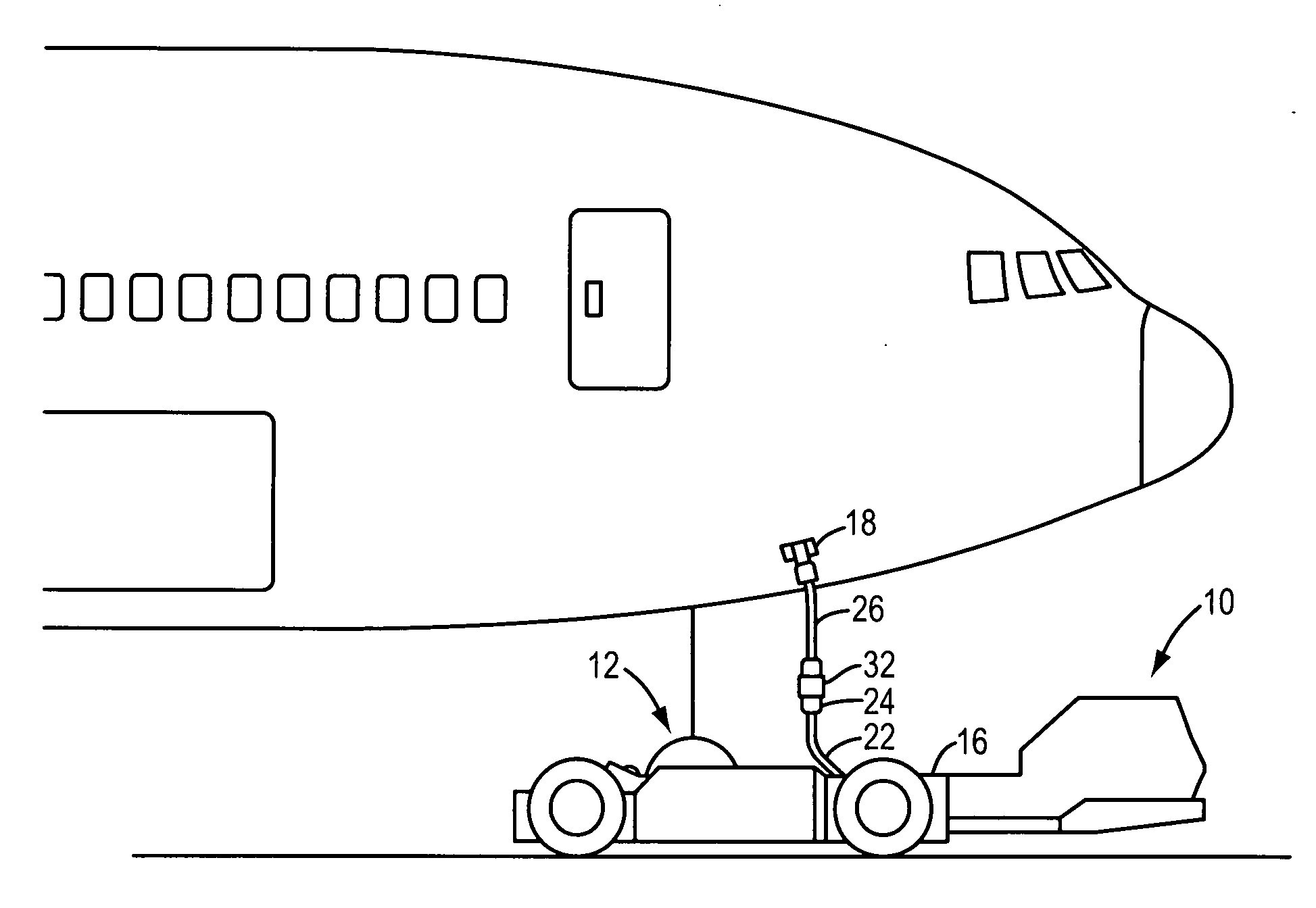
[0034]Referring to FIG. 6, an intermediate cable is shown which includes such means. In this embodiment of the invention, the intermediate cable 26′ includes a plug 30′ which is connected to a first end 34 of an extension pole 36, the opposite end of which may be provided with a handle 38. The extension pole 36 is of sufficient length to allow the operator to insert the plug 30′ into the GPU receptacle 18 while standing on the ground. After the plug 30′ is connected to the GPU receptacle 18, the extension pole 36 remains connected to the intermediate cable 26′ to facilitate the unplugging of the intermediate cable from the GPU receptacle when power from the GPU 16 is no longer needed.

second embodiment

[0035]Referring to FIG. 7, an intermediate cable is shown which includes means to facilitate the connection of the intermediate cable to a GPU receptacle 18 which is located a considerable distance above the ground. In this embodiment of the invention, the intermediate cable 26″ includes a plug 30″ to which a socket 40 is attached. The socket 40 includes an aperture 42 which is configured to receive an end 44 of an extension pole 46, the opposite end of which may be provided with a handle 48. As shown in FIG. 7, the handle end of the extension pole 46 may also include a hook 50 which the operator may use to guide the intermediate cable 26″ away from the tractor 10 as the tractor is positioned around the nose landing gear 12. Similar to the extension pole 36, the extension pole 46 is of sufficient length to allow the operator to insert the plug 30″ into the GPU receptacle 18 while standing on the ground. In this embodiment of the invention, after the intermediate cable 26″ is connect...


PUM

PropertyMeasurementUnit
Lengthaaaaaaaaaa

Abstract

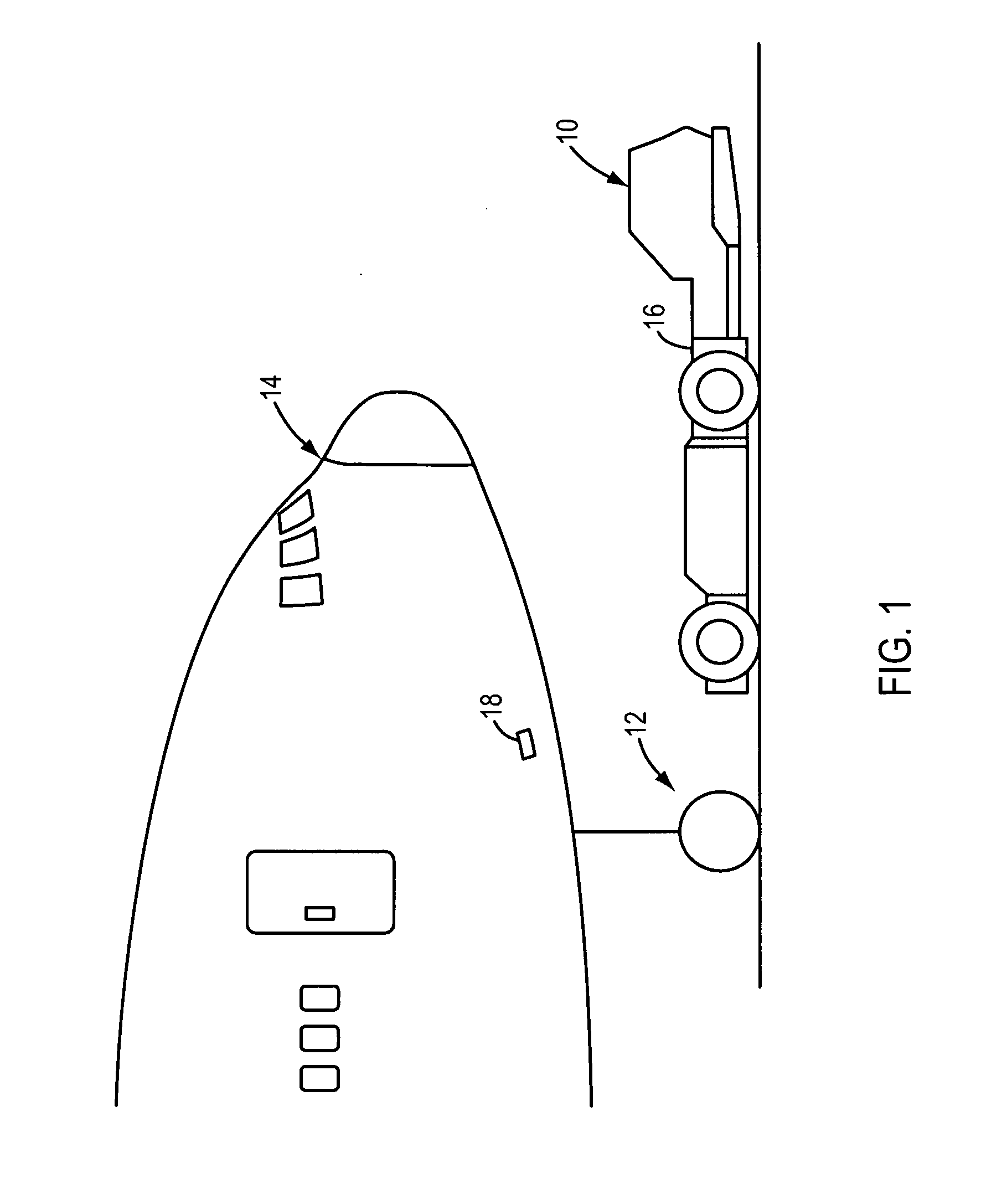
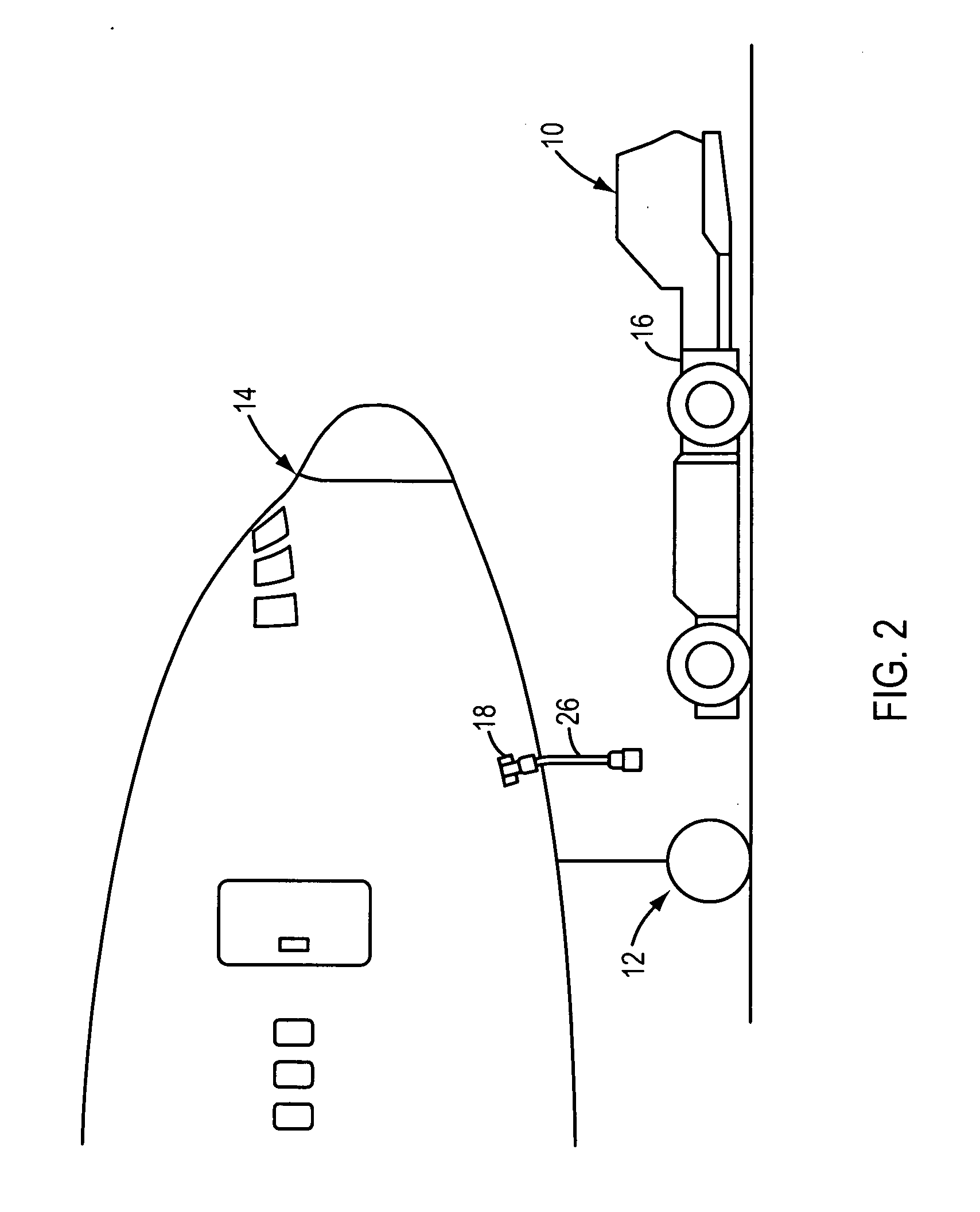
A GPU connection apparatus for an aircraft towing vehicle comprising a vehicle-mounted ground power unit (GPU). The GPU includes a GPU cable having a first end which is connected to the GPU and a second end which includes a GPU connector that is configured to be plugged into a GPU receptacle on an aircraft to be towed. The GPU connection apparatus includes an intermediate cable having a first end which comprises a cable plug and a second end which comprises a cable receptacle. The cable plug is configured to be plugged into the GPU receptacle. In addition, the cable receptacle is configured to receive the GPU connector. In use of the GPU connection apparatus, the cable plug is plugged into the GPU receptacle and the GPU connector is plugged into the cable receptacle to thereby electrically connect the aircraft to the GPU.

Description

[0001]This application is based on and claims the benefit of U.S. Provisional Patent Application No. 61 / 401,321 filed on Aug. 8, 2011.BACKGROUND OF THE INVENTION[0002]The present invention relates to a method and apparatus for connecting a ground power unit (GPU) to an aircraft. More particularly, the invention relates to a method and apparatus for connecting a towbarless tractor-mounted GPU to the aircraft using an intermediate cable and / or towbarless tractor which is configured to prevent the cable from being damaged by the wheels or clamping mechanism of the tractor as it is approaching and clamping onto the aircraft's nose landing gear.[0003]GPU's are used to provide temporary power to an aircraft as it is parked, e.g., at an airport terminal gate. Prior art GPU's are typically stationary devices which are positioned, among other locations, adjacent the gate. Thus, when the aircraft is being towed from the gate to, e.g., a hangar, it must be disconnected from the GPU. As the air...

Claims


Application Information

Patent Timeline
IPC IPC(8): H01R33/92H01R43/26
CPCY10T29/49117B64F1/227
Inventor THOMAS, LARRY
Owner JBT AEROTECH CORP
Why Eureka
Try Eureka